Table of Contents

Subscribe to Our Youtube Channel
Related Manuals for Ideal Boilers RD1


Summary of Contents for Ideal Boilers RD1
- Page 1 INSTALLATION & SERVICING M A N U A L See reverse for RD1 Users Guide British/Scottish Gas RD1 the wall hung boiler RD109, RD112, RD115, RD118, RD121, RD124, RD130 Wall hung, gas fired fanned flue boiler October 2003 UIN 200 548 A01...
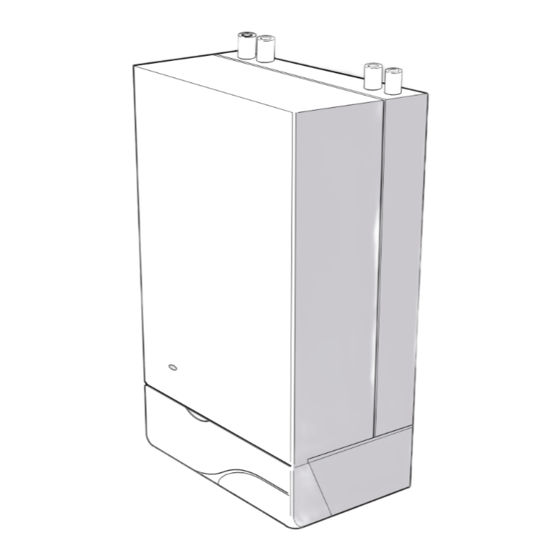
- Page 2 British Gas: (Any internal reference to British Gas applies equally to Scottish Gas) The British Gas RD1 is a range of cast iron wall mounted fanned flue gas central heating boilers. A complete range of natural gas models is available.
- Page 3 /h - divide the gross heat input (Btu/h) by the gross C.V. of the gas (Btu/ft NOTE TO THE INSTALLER: LEAVE THESE INSTRUCTIONS ADJACENT TO THE GAS METER. ALSO COMPLETE THE BENCHMARK LOG BOOK AND GIVE THIS TO THE CUSTOMER. British Gas RD1 - Installation & Servicing...
-
Page 4: Table Of Contents
For condensing boilers only Central heating mode Condensate drain ..........n/a Heat input ..........to be calculated For all boilers: complete, sign & hand over to customer For assistance see Technical Helpline on the back page British Gas RD1 - Installation & Servicing... - Page 5 Detailed Where installation will be in an unusual location, special recommendations are contained in the following British procedures may be necessary and BS.6798 gives detailed Standard Codes of Practice: guidance on this aspect. British Gas RD1 - Installation & Servicing...
- Page 6 (For this purpose a minimum clearance of 12mm is required between the top of the boiler and pelmet or other similar obstruction. British Gas RD1 - Installation & Servicing...
-
Page 7: Air Supply
MUST be protected by a purpose designed guard. cupboard/compartment, are specified in Table 4 and are related to maximum rated heat input. British Gas RD1 - Installation & Servicing... -
Page 8: Electrical Supply
0.74 0.69 1.05 1.39 1.83 2.58 3.54 using the bath or shower. See Frame 31 for details. Maximum boiler operating temperature should be 82 C (180 British Gas RD1 - Installation & Servicing... - Page 9 Note. The pump manufacturers minimum requirements must be complied with All dimensions in mm (in.). N.B. Imperial dimensions are approximate British Gas RD1 - Installation & Servicing...
- Page 10 300mm (12") below the make-up easily seen from the filling point and should preferably be vessel on the return side of the domestic hot water connected at the same point as the expansion vessel. cylinder or radiators. British Gas RD1 - Installation & Servicing...
- Page 11 59.2 28.2 50.0 22.9 30.0 42.9 25.8 36.8 65.1 31.0 55.0 25.0 32.7 46.8 28.2 40.2 71.1 33.9 60.0 Multiplying factors for other system volumes 0.0833 0.109 0.156 0.094 0.134 0.237 0.113 0.20 British Gas RD1 - Installation & Servicing...
- Page 12 Flue baffles. Main burner. 5A. Pumped return pipe. Tie rods. Wall mounting plate. Control box . Collector hood assembly. 4A. Pumped flow pipe. Back panel. Pressure switch. Combustion chamber. 4B. Gravity return pipe. Fan. British Gas RD1 - Installation & Servicing...
- Page 13 Duct cutting support, 2 off (cardboard ) Terminal wall plate, 1 off. Terminal grille assy., 1 off. Polyurethane foam seal 400 lg., 1 off. No. 8 x 8 lg. Pozi pan hd. screws, 3 off. British Gas RD1 - Installation & Servicing...
- Page 14 3. Screw the panel rear assembly (supplied in the kit) to the back of the boiler controls compartment. 4. Proceed with the installation with particular reference to Frames 12, 15, 16, 18, 22 and 23. British Gas RD1 - Installation & Servicing...
- Page 15 Refer to Frame 12. 2. When cutting the ducts, always use the cardboard support rings provided. LEGEND 3. Flue assembly. 1. Terminal. 4. Boiler sealing ring. 2. Weather seal. 5. Flue extension tube. British Gas RD1 - Installation & Servicing...
- Page 16 The side of the casing nearest the flue outlet. marked depending on whether the downward routing pipe brackets are used or not). 5. Remove both templates from the wall. Note. Mark the centre of the hole as well as the circumference. British Gas RD1 - Installation & Servicing...
- Page 17 4. Cut to length X, using the cardboard ring for support. 5. Remove cardboard ring and remove any burrs. For flue lengths greater than 600mm refer to Frames 26 & 27 - Flue extension ducts. British Gas RD1 - Installation & Servicing...
- Page 18 1. Split the side outlet plate into 2 down the split line. 2. Fit the 2 halves of the side outlet plate to the wall, ensuring they are behind the boiler sealing ring. British Gas RD1 - Installation & Servicing...
- Page 19 Secure with the screw attached to the elbow. Note. The sealing ring studs will locate in the back panel one way only. This will ensure that the terminal grille is correctly aligned. British Gas RD1 - Installation & Servicing...
- Page 20 1550 to 2500 B Pack 1 off + D Pack, 2 off see Frame 12 2500 to 3000 B Pack 1 off + D Pack, 3 off see Frame 12 Note. Side flue shown. British Gas RD1 - Installation & Servicing...
- Page 21 5. Secure the mains lead with the cable clamp. Note. IMPORTANT. For gravity DHW applications the pump MUST be wired Control switching must not take place in this mains supply. through the programmer and NOT directly to PL & PN. British Gas RD1 - Installation & Servicing...
-
Page 22: External Controls
2. A frost thermostat should be sited in a cool place in the house, Advice on required modifications to the wiring may be but where it can sense heat from the system. obtained from the component manufacturers. British Gas RD1 - Installation & Servicing... - Page 23 4. Switchmaster (Smiths) valves are similar but the wiring is different. Consult the diagram supplied with valve. LEGEND pk pink blue bk black violet brown white grey yellow y/g yellow/green orange British Gas RD1 - Installation & Servicing...
- Page 24 IMPORTANT.The pump must NOT Pump be wired directly into the boiler. white LEGEND y/g yellow/green blue grey bk black Boiler terminal orange brown strips violet Mains pk pink yellow Typical Programmer British Gas RD1 - Installation & Servicing...
- Page 25 3. Retighten the union and check for gas soundness. WARNING. Whilst effecting the required gas soundness test and purging air from the gas installation open all windows and doors, extinguish naked lights and DO NOT SMOKE. British Gas RD1 - Installation & Servicing...
-
Page 26: Initial Lighting
Remove the control box securing screws and swing it 18. Swing the control box back into its working position and down into the servicing position. See diagram B, secure. Frame 41. British Gas RD1 - Installation & Servicing... -
Page 27: Installation
British Gas Services, details of which are outlined in the the system remaining inoperative during frosty conditions. household pack supplied with this boiler. British Gas RD1 - Installation & Servicing... - Page 28 2. Remove the fixing screws and swing the control box down into the servicing position. Refer to Frame 53. 3. Remove the hot surface igniter securing screw and disengage from the combustion chamber. British Gas RD1 - Installation & Servicing...
- Page 29 9. Refit the boiler casing (Refer to Frame 40). Note that it is not necessary to disturb the controls casing pod. 3. Refit the positive pressure tubes on the top of the fan housing. Reconnect the electrical leads. 10. Close the controls door. British Gas RD1 - Installation & Servicing...
- Page 30 8. Fit the new thermostat and reassemble in reverse order. 9. Check the reset button on the new thermostat is pressed in. 10. Check the operation of the boiler. British Gas RD1 - Installation & Servicing...
- Page 31 Ensure that there is an inlet 5. Replace the pilot burner (injector if necessary) and retain pressure of 20 mbar available. with the M4 screw previously removed. Ensure that the British Gas RD1 - Installation & Servicing...
- Page 32 5. Fit the new burner, ensuring that the retention tab is correctly located in the air box slot and re-assembly in reverse order. 6. Check the burner for cross-lighting and flame stability. British Gas RD1 - Installation & Servicing...
- Page 33 2. Remove the fixing screws and swing the control box down To change the fuse, prise the top off the holder and into the servicing position. disengage the fuse. Refer to Frame 32 for fuse location. British Gas RD1 - Installation & Servicing...
- Page 34 2. Remove the old seal from the casing surround and thoroughly clean the casing surfaces. 3. Fit the new self adhesive seals. 4. Replace the boiler casing. Model RD130 does not have air deflector baffles fitted to the casing bottom. British Gas RD1 - Installation & Servicing...
- Page 35 Pump overrun. Off. Lockout. Flash < 1/second. Off. Sensor Faults Flash > 1/second. Off. Reverse polarity. Flash > 1/sec alternately with LED 4. Flash > 1/sec alternately with LED 3. Refer to Frame 68 British Gas RD1 - Installation & Servicing...
-
Page 36: Rd109
173 596 Controls casing door complete (white) 173 597 (silver) 173 598 E85-313 Casing seal kit (white) 171 479 (silver) 173 588 386 144 Overheat thermostat 171 950 E72-832 Lockout reset switch 171 497 British Gas RD1 - Installation & Servicing... - Page 37 11. Air box and pilot assembly. 16. Pilot shield. LEGEND 12. Main burner. (Numbers up to 51 relate to the B.G. spares list) 17. Gas control valve. 13. Main burner injector. 10. Burner manifold 42. Gas service cock. British Gas RD1 - Installation & Servicing...
- Page 38 68 CONTROL BOX - Exploded View LEGEND Control box. 21A. Thermostat potentiometer. Fuse Thermostat knob. 23A. Printed circuit board. 58A. Lockout reset switch. LED 1 LED 2 LED 3 LED 4 69 BOILER CASING ASSEMBLY British Gas RD1 - Installation & Servicing...
- Page 39 NOTES British Gas RD1 - Installation & Servicing...
- Page 40 This boiler is exclusively manufactured for British Gas by Ideal Boilers CERTIFIED PRODUCT Manufactured under a BS EN ISO 9001: 2000 Quality System accepted by BSI The code of practice for the installation, commissioning & servicing of central heating systems British Gas pursues a policy of British Gas Services Limited.
Need help?
Do you have a question about the RD1 and is the answer not in the manual?
Questions and answers