Table of Contents
Advertisement
Quick Links
NATURAL GAS MODELS (V)TC36NE SERIES
PROPANE/LP GAS MODELS (V)TC36PE SERIES
WARNING: If the information in this manual is not fol-
lowed exactly, a fire or explosion may result causing
property damage, personal injury or loss of life.
Do not store or use gasoline or other flammable vapors
and liquids in the vicinity of this or any other appliance.
WHAT TO DO IF YOU SMELL GAS
• Do not try to light any appliance.
• Do not touch any electrical switch
• Do not use any phone in your building.
• Immediately call your gas supplier from a neighbor's
phone. Follow the gas supplier's instructions.
• If you cannot reach your gas supplier, call the fire
department.
This appliance may be installed in an aftermarket*, permanently located, manufactured (mo-
bile) home, where not prohibited by state or local codes.
This appliance is only for use with the type of gas indicated on the rating plate. This appliance
is not convertible for use with other gases, unless a certified kit is used.
*Aftermarket: Completion of sale, not for purpose of resale, from the manufacturer.
FOR YOUR SAFETY
FOR YOUR SAFETY
Save this manual for future reference.
For more information, visit www.desatech.com
DIRECT-VENT FIREPLACE
OWNER'S OPERATION AND
INSTALLATION MANUAL
WARNING: Improper installation,
adjustment, alteration, service or
maintenance can cause injury or
property damage. Refer to this
manual for correct installation
and operational procedures.
For assistance or additional
information consult a qualified
installer, service agency or the
gas supplier.
Installation and service must
be performed by a qualified
installer, service agency or the
gas supplier.
Advertisement
Table of Contents

Related Manuals for Desa VTC36GPE Series

Summary of Contents for Desa VTC36GPE Series
- Page 1 DIRECT-VENT FIREPLACE OWNER’S OPERATION AND INSTALLATION MANUAL NATURAL GAS MODELS (V)TC36NE SERIES PROPANE/LP GAS MODELS (V)TC36PE SERIES WARNING: If the information in this manual is not fol- WARNING: Improper installation, lowed exactly, a fire or explosion may result causing adjustment, alteration, service or property damage, personal injury or loss of life.
-
Page 2: Table Of Contents
TABLE OF CONTENTS SAFETY INFORMATION TABLE OF CONTENTS CLEANING AND MAINTENANCE ..........25 SAFETY INFORMATION ..............2 TROUBLESHOOTING ...............26 PRODUCT IDENTIFICATION ............3 REPLACEMENT PARTS ............28 LOCAL CODES ................3 SERVICE HINTS ................28 PRODUCT FEATURES ..............4 TECHNICAL SERVICE ..............28 PRE-INSTALLATION PREPARATION.........4 SPECIFICATIONS ..............29 LOCATION OF TERMINATION CAP ..........6 ILLUSTRATED PARTS BREAKDOWN AND PARTS LIST .. -
Page 3: Product Identification
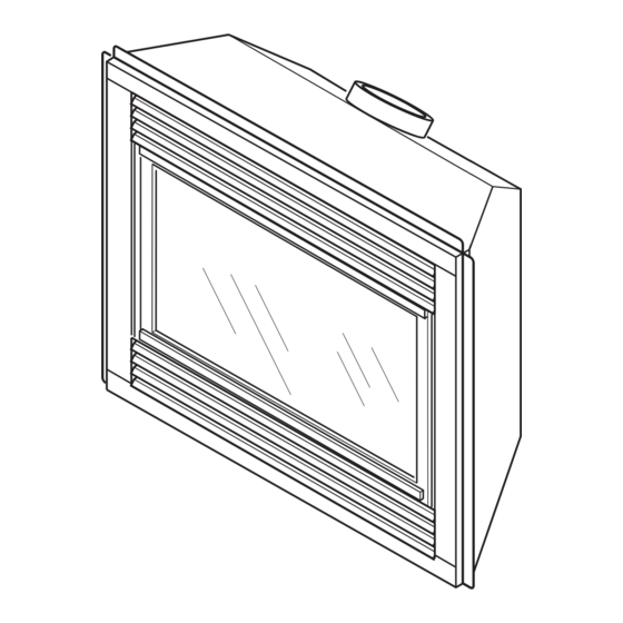
SAFETY INFORMATION PRODUCT IDENTIFICATION LOCAL CODES SAFETY INFORMATION PRODUCT IDENTIFICATION Continued Upper Louver Panel Flue Collar This fireplace reaches high temperatures. Keep children and adults away from hot surfaces to avoid burns or clothing igni- tion. Fireplace will remain hot for a time after shutdown. Allow surfaces to cool before touching. -
Page 4: Product Features
PREPARATION LOCATION AND SPACE REQUIREMENTS Through exterior wall Determine the safest and most efficient location for your DESA enclosed in a chase direct-vent fireplace. Make sure that rafters and wall studs are not in the way of the venting system. Choose a location where the heat... - Page 5 PRE-INSTALLATION PREPARATION Clearances Framing and Finishing PRE-INSTALLATION PREPARATION Continued " 15" " " CLEARANCES Minimum clearances to combustibles for the fireplace are as follows: *Back and sides 0"/mm Perpendicular walls 6" (152 mm) " 41" Floor 0"/mm " Ceiling to louver opening 42" (1067 mm) Nailing Tabs Front 36"...
-
Page 6: Location Of Termination Cap
LOCATION OF TERMINATION CAP LOCATION OF TERMINATION CAP Fixed Openable Fixed Closed Closed Openable TERMINATION CAP GAS METER RESTRICTED AREA AIR SUPPLY INLET (TERMINATION PROHIBITED) A = clearance above grade, veranda, porch, deck, or balcony I = clearance to service regulator vent outlet [*72 inches (182.9cm) [*12 inches (30.5mc) minimum] minimum] B = clearance to window or door that may be opened... -
Page 7: Venting Installation Instructions
• Wear gloves and safety glasses for protection • Use extreme caution when using ladders or when on roof tops These models are tested and approved for use with DESA (direct- vent) pipe components and terminations. • Be aware of electrical wiring locations in walls and ceilings... - Page 8 VENTING INSTALLATION INSTRUCTIONS Installation Planning VENTING INSTALLATION INSTRUCTIONS Male Female Slots Continued Locking Lugs INSTALLATION PLANNING There are two basic types of direct-vent installation: • Horizontal Termination • Vertical Termination Figure 8 - Vent Pipe Connections Horizontal Termination Installation IMPORTANT: Horizontal square terminations require only in- Vent Opening ner portion of wall firestop.
- Page 9 VENTING INSTALLATION INSTRUCTIONS Installation Planning (Cont.) VENTING INSTALLATION INSTRUCTIONS Cut Siding Away Continued to Fit Standoff Standoff WARNING: Do not recess vent termination into Wood Screw any wall. This will cause a fire hazard. Position the horizontal vent Noncombustible Exterior Wall: Vent Cap cap in the center of the 8 "...
- Page 10 45° Elbow Horizontal High Wind Square Termination Wall Firestop Vertical (V) Horizontal (H) " 17" max. 45° Elbow Exterior Portion of Wall Wall Firestop (Round Firestop Termination Only) Horizontal Round Termination Figure 14 - Horizontal Termination Configuration for Square or Round Termination www.desatech.com 116234-01A...
- Page 11 Vertical (V) Required Vertical (V) Vertical Pipe Horizontal (H) " min. None 30" max. " min. 1 ft. 48" max. " min. 2 ft. 60" max. " min. 3 ft. 84" max. " min. 4 ft. 20' max. * Ground Floor Corner Venting Not to Exceed (H) Limits Square...
- Page 12 VENTING INSTALLATION INSTRUCTIONS Installation Planning (Cont.) VENTING INSTALLATION INSTRUCTIONS Continued HORIZONTAL SYSTEM INSTALLATION USING TWO 90° ELBOWS The following configurations show the minimum vertical rise re- quirements for a horizontal system using two 90° elbows. Venting with Two 90° Elbows Horizontal (H Vertical (V) Horizontal (H...
- Page 13 VENTING INSTALLATION INSTRUCTIONS Installation for Vertical Termination VENTING INSTALLATION 2. Assemble the desired lengths of pipe and elbows necessary to reach from the fireplace flue up through the firestop. Be sure all INSTRUCTIONS pipe and elbow connections are fully twist-locked (see Figure Continued 8, page 8).
- Page 14 VENTING INSTALLATION INSTRUCTIONS Installation for Vertical Termination (Cont.) VENTING INSTALLATION INSTRUCTIONS Continued Venting with One 90° Elbow Vertical Termination Configurations Vertical (V) Horizontal (H) Figures 21 through 24 show four different configurations for verti- 5' min. 2' max. cal termination. 6' min.
- Page 15 High Altitude Installation VENTING INSTALLATION HIGH ALTITUDE INSTALLATION INSTRUCTIONS Your DESA direct-vent fireplace has been tested and approved for elevations from 0-2000 feet (USA) and elevations from 0-4500 Continued feet (Canada) . When installing this fireplace at an elevation above 2000 feet (in the USA), you may need to decrease the input rating by changing the existing burner orifice to a smaller size.
-
Page 16: Fireplace Installation
Magnetic Strips Exhaust Port Screw Figure 25 - Blower Model BK www.desatech.com 116234-01A... - Page 17 FIREPLACE INSTALLATION Installing Optional Blower Accessory (Cont.) FIREPLACE INSTALLATION Continued Mount speed control box to switch bracket by placing the plastic control shaft forward through the opening in the switch bracket (see Figure 26). While supporting speed control, secure control shaft with lock nut by pushing and turning lock nut with pliers clockwise until it is tight against front panel.
- Page 18 INSTALLING GAS PIPING TO FIREPLACE LOCATION WARNING: A qualified service person must con- nect fireplace to gas supply. Follow all local codes. CAUTION: For propane/LP units, never connect fireplace directly to the propane/LP supply. This heater requires an external regulator (not supplied). Install the external regulator between the fireplace and propane/LP supply.
- Page 19 FIREPLACE INSTALLATION Installing Gas Piping to Fireplace Location (Cont.) Connecting Fireplace To Gas Supply Checking Gas Connections FIREPLACE INSTALLATION Continued CAUTION: Use only new, black iron or steel pipe. Internally-tinned copper tubing may be used in certain areas. Check your local codes. Use pipe of 1/2"...
- Page 20 Open Equipment Shutoff Valve Closed Equipment Shutoff Propane/LP Valve Supply Tank Gas Valve Figure 34 - Checking Gas Joints for Propane/LP Gas Fireplace www.desatech.com 116234-01A...
- Page 21 FIREPLACE INSTALLATION Removing/Replacing Glass Door (Cont.) Installing Lava Rock and Glowing Embers FIREPLACE INSTALLATION INSTALLING LAVA ROCK AND GLOWING EMBERS Continued It is very important to keep logs exactly as installed. Do not modify Removing Glass Door logs. Only use log set designed for this fireplace. Logs under log/grate If replacement of glass is necessary, the entire assembly, glass and assembly are attached to burner.
- Page 22 FIREPLACE INSTALLATION Installing Optional Brick Liner Models BL36DA(SA) and BL36DHA(SA) Wall Switch Installation Optional Remote Control Installation FIREPLACE INSTALLATION Continued Fireplace Receptacle Remote Control Receiver Ignition Extension Cord Module Plug Figure 40 - Installing the WRC Remote Receiver Battery Cover 12 Volt Battery Back of Pull to Remove...
-
Page 23: Wiring Diagram
WIRING DIAGRAM OPERATING FIREPLACE For Your Safety Read Before Lighting Lighting Instructions WIRING DIAGRAM PILOT IGNITOR LEAD ORANGE BLUE TRANSFORMER WHITE BLACK GROUND GREEN OPERATING FIREPLACE Figure 42 - Turning Equipment Shutoff Valve to the OFF Position www.desatech.com 116234-01A... -
Page 24: Inspecting Burners
OPERATING FIREPLACE To Turn Off Gas To Appliance Optional Remote Operation Operating Optional Blower Accessory INSPECTING BURNERS Pilot Assembly Burner Flame Pattern TO TURN OFF GAS TO APPLIANCE Turn off the wall switch. Turn off all electric power to the appliance if service is to be performed. -
Page 25: Cleaning And Maintenance
CLEANING AND MAINTENANCE Glass Door Pilot and Burners Logs Venting System CLEANING AND Use only the tempered glass door replacement intended for this fireplace (see Replacement Parts, page 28 for detail on ordering). MAINTENANCE No substitutions may be made. See Removing/Replacing Glass Door, page 20 for instructions for replacing glass door. -
Page 26: Troubleshooting
TROUBLESHOOTING TROUBLESHOOTING WARNING: Turn off heater and let cool before servicing. Only a qualified service person should Note: Before troubleshooting the system, make sure the gas service and repair heater. shutoff valve is ON. The two most common causes of a malfunctioning gas appliance are: CAUTION: Never use a wire, needle or similar 1. - Page 27 TROUBLESHOOTING TROUBLESHOOTING Continued WARNING: If you smell gas • Shut off gas supply. • Do not try to light any appliance. • Do not touch any electrical switch; do not use any phone in your building. • Immediately call your gas supplier from a neighbor’s phone. Follow the gas supplier’s instructions.
-
Page 28: Replacement Parts
• purchase date and serial numbers of your heater ready. Usually, we will ask you to return the part to the factory. You can also visit DESAʼs technical service web site at PARTS NOT UNDER WARRANTY www.desatech.com. Contact authorized retailers of this product. If they can not supply original replacement part(s), call DESA at 1-866-672-6040 for referral information. -
Page 29: Specifications
SPECIFICATIONS SPECIFICATIONS 18,000/26,000 Btu/hr 17,500/25,000 Btu/hr Gas Type Natural Propane/LP Ignition Electronic Electronic Manifold Pressure 3.5" w.c. 10.0" w.c. Minimum Inlet Supply Pressure 5.5" w.c. 11.0" w.c. Dimension, Inches/mm (HxWxD) Fireplace (Actual size of firebox. Measurements do not 36" x 41" x 21 "... -
Page 30: Illustrated Parts Breakdown And Parts List
ILLUSTRATED PARTS BREAKDOWN Models TC36NE, VTC36NE, TC36PE, VTC36PE ILLUSTRATED PARTS BREAKDOWN MODELS TC36NE, VTC36NE, TC36PE AND VTC36PE www.desatech.com 116234-01A... - Page 31 PARTS LIST Models TC36NE, VTC36NE, TC36PE, VTC36PE PARTS LIST This list contains replaceable parts used in your fireplace. When ordering parts, follow the instructions listed under Replacement Parts on page 28 of this manual. PART NUMBER TC36NE/PE VTC36NE/PE DESCRIPTION QTY. Firebox Assembly Face Weldment 108010-01...
- Page 32 ILLUSTRATED PARTS BREAKDOWN Models TC36NE, VTC36NE, TC36PE, VTC36PE ILLUSTRATED PARTS BREAKDOWN BURNER ASSEMBLY FOR MODELS TC36NE, VTC36NE, TC36PE AND VTC36PE www.desatech.com 116234-01A...
- Page 33 PARTS LIST Models TC36NE, VTC36NE, TC36PE, VTC36PE PARTS LIST BURNER ASSEMBLY FOR MODELS TC36NE, VTC36NE, TC36PE AND VTC36PE This list contains replaceable parts used in your fireplace. When ordering parts, follow the instructions listed under Replacement Parts on page 28 of this manual. PART NUMBER DESCRIPTION...
-
Page 34: Accessories
fireplace models. Purchase these fireplace accessories from your local retailer. If they can not supply these accessories, call DESAʼs Sales Department at 1-866-672-6040. for information. You can also write to the address listed on the back page of this manual. -
Page 35: Owner's Registration Card
Last Name: Address: City: State: Zip: Country: Home Phone: E-Mail: Please answer the following questions to register your product with DESA: Where will the product be used? � Living/Family Room � Office/Warehouse � Utility Shed/Outbuilding � Garage � Bedroom � Bathroom �... - Page 36 Postage Required 2701 Industrial Drive P.O. Box 90004 Bowling Green, KY 42102-9004 www.desatech.com 116234-01A TAPE...
- Page 37 NOTES ________________________________________________________________________________________________ ________________________________________________________________________________________________ ________________________________________________________________________________________________ ________________________________________________________________________________________________ ________________________________________________________________________________________________ ________________________________________________________________________________________________ ________________________________________________________________________________________________ ________________________________________________________________________________________________ ________________________________________________________________________________________________ ________________________________________________________________________________________________ ________________________________________________________________________________________________ ________________________________________________________________________________________________ ________________________________________________________________________________________________ ________________________________________________________________________________________________ ________________________________________________________________________________________________ ________________________________________________________________________________________________ ________________________________________________________________________________________________ ________________________________________________________________________________________________ ________________________________________________________________________________________________ ________________________________________________________________________________________________ ________________________________________________________________________________________________ ________________________________________________________________________________________________ ________________________________________________________________________________________________ ________________________________________________________________________________________________ ________________________________________________________________________________________________ ________________________________________________________________________________________________ ________________________________________________________________________________________________ ________________________________________________________________________________________________ ________________________________________________________________________________________________ ________________________________________________________________________________________________ ________________________________________________________________________________________________ ________________________________________________________________________________________________ ________________________________________________________________________________________________ ________________________________________________________________________________________________ www.desatech.com 116234-01A...
-
Page 38: Warranty Information
DIRECT-VENT FIREPLACE DESA warrants this product to be free from defects in materials and components for two (2) years from the date of first purchase, provided that the product has been properly installed, operated and maintained in accordance with all applicable instructions. To make a claim under this warranty the Bill of Sale or cancelled check must be presented.
Need help?
Do you have a question about the VTC36GPE Series and is the answer not in the manual?
Questions and answers