Table of Contents
Advertisement
Quick Links
Space-saving Dual Output Signal Conditioners
Mini-MW Series
POTENTIOMETER TRANSMITTER
(PC programmable)
Functions & Features
• Provides two DC outputs proportional to a potentiometeror
slidewire position input
• Two independent output ranges
• Burnout detection
• PC programmable
• High-density mounting
Typical Applications
• Tank levels
• Positions
29.5 (1.16)
89
(3.51)
124
(4.88)
mm (inch)
MODEL: W2XM–1[1][2]-[3][4]
ORDERING INFORMATION
• Code number: W2XM-1[1][2]-[3][4]
Specify a code from below for each [1] through [4].
(e.g. W2XM-1Z1V3-M2/N/Q)
• Total resistance (e.g. 1 kΩ)
• Input range (e.g. 0 – 100 %)
• Output 1 range (e.g. 4 – 20 mA DC)
• Output 2 range (e.g. 1 – 5 V DC)
• Specify the specification for option code 'Q.'
(e.g. /C01/S01)
Note: If one of the outputs should be a current range,
specify it for the Output 1 to allow a greater load.
INPUT
1: Total resistance 75 Ω – 10 kΩ
(Configurator software is used to change the input range.)
SEN TRONIC
AG
Produkte, Support und Service
[1] OUTPUT 1
Current
Z1: Range 0 – 20 mA DC
Voltage
V2: Range -10 – +10 V DC
V3: Range -5 – +5 V DC
(Configurator software is used to change output over the
described range of the selected suffix code.
For changing between suffix codes, set the Output Range
Selector on the side of unit before software adjustment.)
[2] OUTPUT 2
Same range availability as Output 1
Y: None
(Configurator software is used to change output over the
described range of the selected suffix code.
For changing between suffix codes, set the Output Range
Selector on the side of unit before software adjustment.)
[3] POWER INPUT
AC Power
M2: 100 – 240 V AC (Operational voltage range 85 – 264 V,
47 – 66 Hz)
DC Power
R: 24 V DC
(Operational voltage range 24 V ±10 %, ripple 10 %p-p max.)
R2: 11 – 27 V DC
(Operational voltage range 11 – 27 V, ripple 10 %p-p max.)
P: 110 V DC
(Operational voltage range 85 – 150 V, ripple 10 %p-p max.)
[4] OPTIONS (multiple selections)
Standards & Approvlas (must be specified)
/N: Without CE
Other Options
blank: none
/Q: Option other than the above (specify the specification)
SPECIFICATIONS OF OPTION: Q (multiple selections)
COATING (For the detail, refer to M-System's web site.)
/C01: Silicone coating
/C02: Polyurethane coating
/C03: Rubber coating
TERMINAL SCREW MATERIAL
/S01: Stainless steel
RELATED PRODUCTS
• PC configurator software (model: W2CFG)
Downloadable at M-System's web site.
A dedicated cable is required to connect the module to the
Rugghölzli 2
Tel. +41 (0)56 222 38 18
CH - 5453 Busslingen
Fax +41 (0)56 222 10 12
MODEL: W2XM
mailbox@sentronic.com
www.sentronic.com
Advertisement
Table of Contents

Related Manuals for M-system W2CFG


Summary of Contents for M-system W2CFG
- Page 1 • Output 2 range (e.g. 1 – 5 V DC) SPECIFICATIONS OF OPTION: Q (multiple selections) • Specify the specification for option code ‘Q.’ COATING (For the detail, refer to M-System's web site.) (e.g. /C01/S01) /C01: Silicone coating Note: If one of the outputs should be a current range, /C02: Polyurethane coating specify it for the Output 1 to allow a greater load.
-
Page 2: General Specifications
MODEL: W2XM PC. Please refer to the internet software download site or Output range: -10 – +10 V DC the users manual for the PC configurator for applicable Conformance range: -11.5 – +11.5 V DC cable types. Minimum span: 1 V Code V3 (narrow spans) Output range: -5 –... -
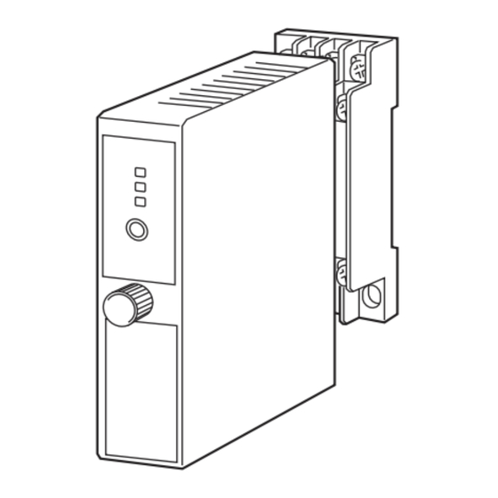
Page 3: External View
MODEL: W2XM CALCULATION EXAMPLES OF OVERALL ACCURACY [Example] Total Resistance 0 – 1.5 kΩ, Input Range 250 – 750 Ω, Output Type -5 – +5 V, Output Range 1 – 5V Max. Input Range (1500 Ω) ÷ Span (500Ω) × 0.01 % + Max. Output Range (10 V) ÷... - Page 4 MODEL: W2XM SCHEMATIC CIRCUITRY & CONNECTION DIAGRAM STATUS DIP SW Isolation POTENTIOMETER max. Digital Output Computation Driver OUTPUT 1 Low Drift – Amplifier DIP SW – Output min. Driver OUTPUT 2 – U(+) CONFIGURATOR JACK POWER V(–) Base Socket Remark: The section enclosed by broken line is only with 2nd output option. Specifications are subject to change without notice.
-
Page 5: Component Identification
The unit is programmable using the PC Configurator Soft- ware. For detailed information on the PC configuration, Connection refer to the W2CFG users manual. The W2CFG PC Con- Diagram figurator Software is downloadable at M-System’s web site: http://www.m-system.co.jp. -
Page 6: Terminal Connections
1) Terminal wiring: Check that all cables are correctly con- types before setting a precise output range using PC Con- nected according to the connection diagram. figurator Software (model: W2CFG). 2) Check DIP switch setting. For detailed information on the PC configuration, refer to 3) Power input voltage: Check voltage across the terminal the W2CFG users manual. -
Page 7: Maintenance
When the output is out of tolerance, recalibrate the unit using the PC Configurator Software (model: W2CFG). LIGHTNING SURGE PROTECTION M-System offers a series of lightning surge protector for protection against induced lightning surges. Please contact M-System to choose appropriate models. SEN TRONIC Rugghölzli 2... -
Page 8: External Dimensions
M-System’s option, the repair, replacement or refund of the purchase price of any M-System product which is defective under the terms of this warranty. To submit a claim under this warranty, the purchaser must return, at its expense, the defective M-System product to the below address together with a copy of its original sales invoice.
Need help?
Do you have a question about the W2CFG and is the answer not in the manual?
Questions and answers