Advertisement
Quick Links
Terra Series
|
AESS-BFM90H500ST
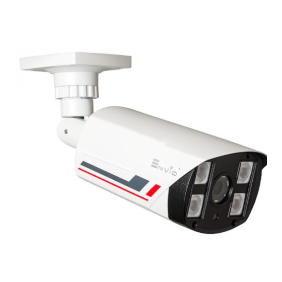
AESS-BFM90H500ST
5MP Bullet Hybrid Camera
Technical Specification
Camera
Image Sensor
1/2.9"SONY STARVIS CMOS
Effective Pixels
2592(H)×1944(V),5MP
Scanning System
Progressive
Minimum Illumination
0.001Lux/F1.6, 30IRE, 0Lux IR on
IR Distance
80m
IR On/Off Control
Auto / Manual
IR LEDs
4 ARRAY IR LED
Lens
Lens Type
Fixed Lens
Focal Length
4mm
Angle of View
78°
Focus Control
N/A
Video
Resolution
2592x1944
Video Output
1-channel BNC high definition video output AHD/HD-TVI
5MP@20FPS;HD-CVI 4MP@25FPS
Day/Night
Auto (ICR) / Manual
OSD Menu
Multi-language
BLC Mode
BLC / HLC / DWDR
WDR
WDR
Gain Control
AGC
Noise Reduction
3D
White Balance
Auto / Manual
Smart IR
Auto / Manual
Eelectrical
Power Supply
12V DC ±30%
Power Consumption
Max 5W (12V DC, IR on)
Analog High Defition
•
1/2.9" SONY STARVIS
•
(2592x1944)
•
4 mm Fixed lens
•
Maximum IR Led distance 80m
•
4in1 AHD, HD-CVI, HD-TVI, CVBS (UTC)
•
4 ARRAY LEDs
•
IP66
•
DC12V
1 Warnings & Precautions
Dear Customer, we thank you for choosing one of our products whose correct use guarantees solutions
of the highest quality and reliability over time. This manual provides instructions for using the product.
2 Connections
Make sure the camera is not powered before making connections. The RG59 video cable is connected to the
female bayonet BNC connector, which is then connected to the DVR. Twisted-pair cables can be used with
balun converters. Check that the power supply is correct for the camera model used. Use 12Vdc / 1A or 1.5A
stabilized power supplies. Beware of power extension cables that are too long or have a small section, which
could introduce an excessive voltage drop. Make sure the camera is not powered before making connections.
The RG59 video cable is connected to the female bayonet BNC connector, which is then connected to the
DVR. Twisted-pair cables can be used with balun converters. Check that the power supply is correct for the
camera model used. Use 12Vdc / 1A or 1.5A stabilized power supplies. Beware of power extension cables that
are too long or have a small section, which could introduce an excessive voltage drop.
The values expressed in the following table are to be considered at a temperature of 20 ° C [68 ° F].
Conductors section
24 AWG
(AWG)
(0,22mm²)
Resistance value
0.078
(Ώ/m)
Voltage drop
0.028
( V/m)
As the copper conductor section increases, there is a decrease in the resistance value () / m) and therefore in
the voltage drop on the cable itself. Therefore, consider carefully the length and section of the cable during the
design phase. Excessive distances between the power supply and the camera could compromise the correct
functioning of the camera. The acceptable standard of variation of the supply voltage is 12Vdc ± 10%
2 Installation
This section indicates how to install the camera on a ceiling or wall with protected cable passage.
Check the solidity of the structure on which you intend to fix the camera, mark the points with a pencil and
drill the holes necessary for its fastening.
2.1 Bullet type camera
The bullet cameras are equipped with an integrated bracket for wall mounting, specially designed to allow the
passage of cables inside it and protect them from tampering attempts. The camera is generally mounted at
the cable outlet so as not to leave exposed cables. However, the fixing base also has a lateral cable outlet slot
if the cables come from the side in the external duct. The bracket must be fixed to the wall or ceiling with the
plugs provided.
3.2 Dome type camera
Dome cameras consist of the camera unit and the fixing base which are screwed together. Before proceeding
with the assembly, the fixing base must be unscrewed, separating it from the camera body. Generally, no
tools are needed to unscrew the fixing base from the camera body, however, if this is tightened too deeply,
you can help yourself by placing a rigid rod, such as a screwdriver, between the
two lateral cable outlet slots located in the base. The fixing base, separated from the camera, is fixed to the
wall or to the wall with plugs in correspondence with the cable outlet hole and the camera body is
subsequently screwed onto it. Before tightening fully, correctly orient the viewing angle.
3.3 Framing adjustment
Once correctly fixed to the wall / ceiling, point it in the desired direction and lock it (it may vary from model to
model) by tightening the screws with the supplied Allen key.
Fixed lens cameras (IR up to 20m) do not require focus as they are factory set for most applications.
To ensure excellent image quality even in low light conditions, all models are equipped with a Day & Night
function with removal of the IR filter to automatically switch from color to B / W. In addition, all models are
equipped with integrated 850nm IR LED illuminators, for adequate illumination of the area being shot. Be
careful not to install the camera very close to strong light sources or in places subject to reflection of light that
could compromise the correct vision of the camera.
4 OSD menu
This model has OSD menu control via both Joystick and coaxial control with XVR:
Access the DVR menu in the appropriate coaxial configuration section (in ENVIO DVRs this setting is called "XVI
control"). Press the central button of the joystick that appears on the monitor to enter the home page of the
menu or press the central button of the joystick on the camera cable.
4.1 Video Standard Setting
It is possible to set the camera in one of the 4 video standards currently on the market (AHD; HD-TVI; HD-CVI;
CVBS). Refer to the image shown in chapter 2 CONNECTIONS.
For the full OSD manual visit www.enviosecurity.com
22 AWG
20 AWG
18 AWG
(0,33mm²)
(0,52mm²)
(0,83mm²)
0.050
0.030
0.018
0.018
0.011
0.006
Web: www.enviosecurity.com
EN
Advertisement

Related Manuals for ENVIO AESS-BFM90H500ST


Summary of Contents for ENVIO AESS-BFM90H500ST
- Page 1 This model has OSD menu control via both Joystick and coaxial control with XVR: Access the DVR menu in the appropriate coaxial configuration section (in ENVIO DVRs this setting is called "XVI control"). Press the central button of the joystick that appears on the monitor to enter the home page of the menu or press the central button of the joystick on the camera cable.
- Page 2 Acest model are control meniu OSD atât prin joystick, cât și prin control coaxial cu XVR: 4 Menu OSD Accesați meniul DVR în secțiunea de configurare coaxială corespunzătoare (în DVR-urile ENVIO această setare se numește „control XVI”). Apăsați butonul central al joystick-ului care apare pe monitor pentru a intra în Questo modello ha il controllo del menu OSD sia tramite Joystick che mediante controllo coassiale con XVR: pagina principală...
Need help?
Do you have a question about the AESS-BFM90H500ST and is the answer not in the manual?
Questions and answers