Table of Contents
Advertisement
Quick Links
Installation Instructions
A/GPDM3 13.4 SEER2 "M" SERIES - Single Package
Dual Fuel Gas-Electric Heating & Cooling Units
Affix this manual and Users Information Manual adjacent to the unit.
ATTENTION INSTALLING PERSONNEL
Prior to installation, thoroughly familiarize yourself with this
Installation Manual. Observe all safety warnings. During
installation or repair, caution is to be observed.
It is your responsibility to install the product safely and to
educate the customer on its safe use.
RECOGNIZE THIS SYMBOL
AS A SAFETY PRECAUTION.
These installation instructions cover the outdoor installation of
single package gas electric heating and cooling units. See the
Specification Sheet applicable to your model* for information
regarding accessories.
*NOTE: Please contact your distributor or our website for the
applicable Specifications Sheets referred to in this manual.
This Forced Air Central Unit Design Complies With Requirements
Embodied in The American National Standard / National Standard
of Canada Shown Below.
ANSI Z21.47•CSA-2.3 Central Furnaces
*NOTE: Please contact your distributor or our website for the
applicable Specification Sheet referred to in this manual.
IOG-3028A
11/2022
19001 Kermier Rd., Waller, TX 77484
www.goodmanmfg.com or www.amana-hac.com
Daikin Comfort Technologies Manufacturing, L.P.
© 2022
is a registered trademark of Maytag Corporation or its related companies and is used under license. All rights reserved.
ONLY PERSONNEL THAT HAVE BEEN TRAINED TO INSTALL,
ADJUST, SERVICE, MAINTENANCE OR REPAIR
(HEREINAFTER, "SERVICE") THE EQUIPMENT SPECIFIED IN
THIS MANUAL SHOULD
SERVICE THE EQUIPMENT. THE MANUFACTURER WILL
NOT BE RESPONSIBLE FOR ANY INJURY OR PROPERTY
DAMAGE ARISING FROM IMPROPER SERVICE OR SERVICE
PROCEDURES. IF YOU SERVICE THIS UNIT, YOU ASSUME
RESPONSIBILITY FOR ANY INJURY OR PROPERTY
DAMAGE WHICH MAY RESULT. IN ADDITION, IN
JURISDICTIONS THAT REQUIRE ONE OR MORE LICENSES
TO SERVICE THE EQUIPMENT SPECIFIED IN THIS
MANUAL, ONLY LICENSED PERSONNEL SHOULD SERVICE
THE EQUIPMENT.
IMPROPER INSTALLATION, ADJUSTMENT, SERVICING,
MAINTENANCE OR REPAIR OF THE EQUIPMENT SPECIFIED
IN THIS MANUAL, OR ATTEMPTING TO INSTALL, ADJUST,
SERVICE OR REPAIR THE EQUIPMENT SPECIFIED IN THIS
MANUAL WITHOUT PROPER TRAINING MAY RESULT IN
PRODUCT DAMAGE, PROPERTY DAMAGE, PERSONAL
INJURY OR DEATH.
DO NOT BYPASS SAFETY DEVICES
WARNING
WARNING
Advertisement
Table of Contents
Troubleshooting

Related Manuals for Amana A/GPDM3 Series


Summary of Contents for Amana A/GPDM3 Series
- Page 1 *NOTE: Please contact your distributor or our website for the DO NOT BYPASS SAFETY DEVICES applicable Specification Sheet referred to in this manual. 19001 Kermier Rd., Waller, TX 77484 www.goodmanmfg.com or www.amana-hac.com Daikin Comfort Technologies Manufacturing, L.P. © 2022 IOG-3028A 11/2022 is a registered trademark of Maytag Corporation or its related companies and is used under license.
-
Page 2: Table Of Contents
TABLE OF CONTENTS APPENDIX ............... 26 TO THE INSTALLER ............2 TROUBLESHOOTING ............. 26 TO THE OWNER .............. 2 Ignition Control Diagnostic Indicator Chart ..27 SHIPPING INSPECTION ..........2 Heating Timing Chart ..........27 SAFETY INSTRUCTIONS ..........2 Cooling/heat pump Timing Chart ......27 ORDERING PARTS ............ - Page 3 FIRE OR EXPLOSION HAZARD Failure to follow the safety warnings exactly could result in serious injury, death or property damage. Never test for gas leaks with an open flame. Use a commercially available soap solution made specifically for the detection of leaks to check all connections.
- Page 4 AVERTISSEMENT RISQUE D'INTOXICATION AU MONOXYDE DE CARBON MONOXIDE POISONING HAZARD CARBONESi les étapes décrites ci-dessous ne sont pas Failure to follow the steps outlined below for each suivies pour chacun des appareils raccordés au système appliance connected to the venting system being de ventilation au moment de sa mise en marche, cela placed into operation could result in carbon monoxide peut entraîner une intoxication au monoxyde de...
-
Page 5: Ordering Parts
Specification sheets can be found at 3. 3. In case of concealed damage, carrier should be www.ama na-hac.com for Amana® brand products. Within notified as soon as possible-preferably within 5 days. the website, please select the residential or commercial 4. -
Page 6: Pre-Installation Checks
d. Copy of the inspection report issued by carrier sources of chlorine/fluorine compounds. representative at the time damage is reported to • To avoid possible illness or death of the building the carrier. The carrier is responsible for making occupants, do NOT locate outside air intake device prompt inspection of damage and for a thorough (economizer, manual fresh air intake, motorized fresh investigation of each claim. -
Page 7: Rooftop Installations Only
Outside Slab Installation Rooftop Installations Only: NOTE: To ensure proper condensate drainage, unit must be installed in a level position. • To avoid possible property damage or personal injury, the roof must have sufficient structural strength to carry the weight of the unit(s) and snow or water loads as required by local codes. -
Page 8: Gas Piping
The gas/electric units naturally derate with altitude. Do not attempt to increase the firing rate by changing orifices or increasing the manifold pressure. This can cause poor combustion and equipment failure. At all altitudes, the manifold pressure must be within 0.3 inches W.C. of that listed on the nameplate for the fuel used. - Page 9 • Listed gas appliance connectors used in accordance with the terms of their listing that are completely in the same room as the equipment In the preceding two methods the connector or tubing must be protected from physical and thermal damage. Aluminum alloy tubing and connectors must be coated to protect against external corrosion when in contact with masonry, plaster or insulation or are subject to repeated wettings by...
-
Page 10: Electrical Wiring
ELECTRICAL WIRING 5 to 15 PSIG First Stage (20 PSIG Max.) Regulator Continuous 11" W.C. 200 PSIG Second Stage Maximum Regulator NOTE: All wiring should be made in accordance with the National Electrical Code. Consult your local Power Company to determine the Typical Propane Gas Piping availability of sufficient power to operate the unit. -
Page 11: High Voltage Wiring
equipped with a single-pole contactor. Exercise caution A/GPDM3 24-48 when servicing as only one leg of the power supply is TERMINAL WIRE THERMOSTAT broken with the contractor. R (24V) High Voltage Wiring Green G (Fan) Rated Voltage Minimum Supply Voltage Maximum Supply Voltage Orange O (Rev. -
Page 12: Horizontal Air Flow
Horizontal Air Flow Filters Single phase models are shipped without horizontal duct covers. If needed, these kits may be ordered through Goodman’s Service Parts department. Down Discharge Applications Cut insulation around bottom openings and remove panels from the bottom of the unit, saving the screws holding the Even though a return air filter is not supplied with this unit, panels in place. -
Page 13: Condensate Drain
HEAT PUMP OPERATION Heating Cycle The heat pump operates in the heating cycle by redirecting refrigerant flow through the refrigerant circuit external to the compressor. This is accomplished through the reversing valve. Hot discharge vapor from the compressor is directed to the indoor coil (evaporator on the cooling cycle) where the heat is removed, and the vapor condenses to liquid. -
Page 14: Heat Pump Mode Operation Sequence Of Operation
Outdoor Thermostat For optimal performance, a dual fuel thermostat with an outdoor temperature sensor should be used. TSTATGTS3275 (Emerson Dual Fuel thermostat) with TSTATTSORS (outdoor temperature sensor) is recommended. This will allow the installer to control when the unit switches from heat pump to gas heat based on a set point entered into the thermostat. -
Page 15: Defrost Cycle
6. The 30-second HEAT FAN ON delay time begins Upon a call for defrost, the blower will continue to run after the main burners light. and the defrost board will send a W1 signal to the ignition control. At the same time the compressor will stop for 30 7. -
Page 16: Air Flow Measurement And Adjustment
thermostat call for FAN is removed. The rollout protection device opens, cutting power to the gas valve, if the flames from the burners are not properly Air flow Measurement and Adjustment drawn into the heat exchanger. The rollout protection Please review the Duct Work section before proceeding device is located on the burner bracket. - Page 17 7. Wait five minutes to clear out any gas. Inlet gas pressure can also be measured by removing the cap from the drip leg and installing a 8. Smell for gas, including near the ground. This is predrilled cap with a hose fitting. important because some types of gas are heavier than air.
- Page 18 valve external to the furnace. meter for one complete revolution. If this is a 2 cubic foot dial, divide the seconds by 2; if it is a 1 cubic foot 2. Turn off all electrical power to the system. dial, use the seconds as is. This gives the seconds 3.
-
Page 19: Suggested Field Testing Troubleshooting
3. If the outdoor ambient is above 80°F, the unit may trip DF1 and DF2 on the board. Should read line voltage on its high-pressure cutout when in heating mode. The (208-230 VAC) indicating the relay is open in the compressor should stop. - Page 20 3. Add the two readings togther. NOTE: Both readings may be taken simultaneously and read directly on the manometer if so desired. 4. Consult proper table for quantitu of air. If the external static pressure exceeds the minimum or maximum allowable statics, check for closed dampers, dirty filters, undersizd or poorly laid out ductwork.
-
Page 21: Cooling Start-Up
Limit Check Cooling Start-up Check limit control operation after 15 minutes of operation by blocking the return air grille(s). 1. After several minutes the main burners must go OFF. Blower will continue to run. 2. Remove air restrictions and main burners will relight after a cool down period of a few minutes. -
Page 22: Troubleshooting
Refrigerant Charge Check Cooling Operation NOTE: Mechanical cooling cannot be reliably provided at NOTE: For optimal performance, follow charging instruc- ambient temperatures below 50° F. tions below. (Units with Fixed Orifice Devices) 1. Turn on the electrical power supply to the unit. All package units with fixed orifice devices are charged 2. - Page 23 new ignition sequence. If flame is established then lost on and limit. This limit will automatically reset once the subsequent attempts, the control will recycle the ignition temperature falls below a preset level. sequence. Auxiliary/Secondary Limit The diagnostic fault code is 1 flash for a lockout due A dirty filter, excessive duct static, insufficient air flow, a to failed ignition attempts.
-
Page 24: Maintenance
motor and the combustion fan motor are permanently not started after three minutes, wait an additional five lubricated. No additional oiling is required. minutes to allow the thermostat to complete its short cycle delay time. Flame Sensor (Qualified Servicer Only) A drop in the flame current can be caused by a nearly High Pressure Switch/Loss of Charge Switch invisible coating on the flame sensor. -
Page 25: Accessories And Functional Parts
Check the burner flames for: 1. Good adjustment 2. Stable, soft and blue 3. Not curling, floating, or lifting off. For further information on the yearly inspection, consult the User Manual. It is recommended that a qualified servicer Burner Flame inspect and service the unit at least once each year. -
Page 26: Appendix
APPENDIX TROUBLESHOOTING DIAGNOSTIC CHECK CHECK STATUS LED - RED NORMAL OPERATION CHECK INPUT POWER NO POWER OR INTERNAL CONTROL CHECK FUSE(S) FAULT GAS FLOW GAS PRESSURE 1 FLASH IGNITION FAILURE GAS VALVE FLAME SENSOR CHECK PRESSURE SWITCH 2 FLASHES PRESSURE SWITCH OPEN CHECK TUBING CHECK VENT MOTOR PRESSURE SWITCH CLOSED... -
Page 27: Ignition Control Diagnostic Indicator Chart
IGNITION CONTROL DIAGNOSTIC INDICATOR CHART Red Light Signal Refer to Abnormal Heating or Cooling Operation Sections of this Manual Internal Control Failure 1 Flash External Lockout 2 Flashes Pressure Switch Stuck Open 3 Flashes Pressure Switch Stuck Closed 4 Flashes Thermal Protection Device Open 5 Flashes Flame Detected with Gas Valve Closed... -
Page 28: Unit Demensions
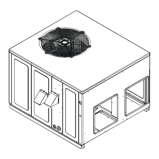
UNIT DIMENSIONS Unit Dimensions (Inches) Chassis Model Height Size A/GPDM3 24-36 34 1/2 Medium A/GPDM3 42-48 42 1/2 Large Duct Openings Model Supply Return A/GPDM3 24-36 A/GPDM3 42-48... -
Page 29: Wiring Diagrams
WIRING DIAGRAM SEE NOTE 7 S R C SEE NOTE 8 COMP SEE NOTE 4 RCCF C-RV R-PS1 O-RV LVDR BL/PK BL/PK HVDR R-DFT P1 - PIN # 1 SEE NOTE 2 P1 - PIN # 6 P1 - PIN # 8 P1 - PIN # 3 P1 - PIN # 5 P1 - PIN # 2... - Page 30 WIRING DIAGRAM SUPPLY VOLTAGE 208-230/1/60 COMPONENT LEGEND SEE NOTE 7 AUXILLARY LIMIT SWITCH FACTORY WIRING CONTACTOR CRANKCASE HEATER LINE VOLTAGE SEE NOTE 8 CRANKCASE HEATER SWITCH LOW VOLTAGE CONDENSER MOTOR COMP OPTIONAL HIGH COMP COMPRESSOR RCCF C VOLTAGE DEFROST CONTROL BOARD DEFROST THERMOSTAT DEFROST RELAY FIELD WIRING...
-
Page 31: Blower Performance Data
BLOWER PERFORMANCE DATA A/GPDM32406041A* - Rise Range: 25° - 55° Stage Heating Speed Stage Heating Speed Cooling Speed Cooling Speed Cooling Speed E.S.P WATTS RISE WATTS RISE WATTS WATTS WATTS 1069 1054 1174 1020 1007 1134 1093 1050 1007 A/GPDM33008041A* - Rise Range: 35° - 65° Stage Heating Speed Stage Heating Speed Cooling Speed... - Page 32 BLOWER PERFORMANCE DATA A/GPDM34210041A* - Rise Range: 35° - 65° Stage Heating Speed Cooling Speed Cooling Speed Cooling Speed Stage Heating Speed E.S.P WATTS RISE WATTS RISE WATTS WATTS WATTS 1098 1423 1354 1535 1677 1038 1375 1296 1489 1633 1322 1237 1440...
-
Page 33: Start-Up Checklist
Start-Up Checklist Residential Package - (Indoor Section) Model Number Serial Number ELECTRICAL Line Voltage (Measure L1 and L2 Voltage) L1 - L2 Secondary Voltage (Measure Transformer Output Voltage) R - C Blower Amps Heat Strip 1 - Amps Heat Strip 2 - Amps BLOWER EXTERNAL STATIC PRESSURE Return Air Static Pressure IN. - Page 34 THIS PAGE IS INTENTIONALLY LEFT BLANK...
- Page 35 THIS PAGE IS INTENTIONALLY LEFT BLANK...
- Page 36 That’s why we know. . .There’s No Better Quality. That’s why we know. . .There’s No Better Quality. Visit our website at www.goodmanmfg.com or www.amana-hac.com for information on: • Products •...
Need help?
Do you have a question about the A/GPDM3 Series and is the answer not in the manual?
Questions and answers