
Related Manuals for Soundstream MC-140X


Summary of Contents for Soundstream MC-140X
- Page 1 MC 140x Multi-Channel 140 Watt Amplifier with Staggered Electronic Crossover MC 245 Khannel 240 Watt Amplifier With Staggered Electronic Crossover OWER’S MANUAL...
-
Page 2: Crossover Network
MC140x Thank you for purchasing the Soundstream MC140” or MC245 You now own one of the finest amplifier/electronic crossover combinations made, a precision component capable Multi-Channel of audiophile quality performance. 140 Walt Am lifier with To get the most out of your unit, we suggest that you acquaint yourself with its capabilities Stagge tJEktronic and design. -
Page 3: Design Features
The MC 140x/245 provide superior, non-intrusive protection from overheating in two ways: First, the Soundstream “Chassisink” has been custom designed to guarantee the lowest possible thermal resistance (maximum cooling), greatly reducing the possibility of over- heating. Secondly, if this should occur, all Soundstream amplifiers incorporate our “Smart Power Supply”... -
Page 4: Installation
In the last nine pages of this manual you will find several system configuration diagrams. Please review the pages appropriate to the amplifier model you have purchased. Both these Soundstream amplifiers offer a variety of available configurations. Please use the configu- ration that best suits your installation needs. - Page 5 MC140” - Sekting Operating Mode The 140 watts available from the MC 140x can be divided into two channels (stereo) three channels (stereo plus a single mono channel) or four channels (front and rear stereo; or stereo bi-amp). To select any of these modes, remove the access hatch on the bottom of the amplifier and set the internal switches marked stereo/mono to the desired mode of operation.
-
Page 6: Input Connections
For connection from your unit to the amplifier(s), we recommend the use of Soundstream DL.1 or an equivalent premium cable. In most cases, the signal source will be the preamp output jacks of a head unit. However, some connectors other than the RCA type. In this case you will need a special adapter to convert from the source configuration to RCA. -
Page 7: Output Connections
- Spkr Out / STANDARD Output Connections Use Soundstream High Definition speaker cable (such as Speaker 120 or 160) or an for best results. The terminals of your loudspeakers are marked for polarity, and equivalent the speaker wire should be coded by color or markings on the iacket. Be sure to connect the ieft and right h c annels with the same polarity. -
Page 8: Input Level Adjustments
For Power, Ground and Remote connections, we recommend Soundstream premium cable (such as Power 80 or loo), or an equivalent. A minimum of 10 gauge power and ground cable should be used on both of these amplifiers in order to realize maximum performance. -
Page 9: Protection Circuits
Because of the Your “Smart Power Supply”, it is unlikely that the amplifier will shut down due to thermal overload. Your Soundstream amplifier is protected by a limited warranty. Please read the warran?/ SERVICE information enclosed with this product. SPECIFICATIONS... -
Page 10: Front Panel Connections
Front Panel Connections MC 245 multiDk ChOnne( two h u n d r e d for& watt pow& amplifier / ekctronlc cro&er MONO OUTPUT CONNECTORS Remote to Chassis Ground Fuse to +12v Battery Terminal Subwoofers Hz 12dB/Oct Bottom Panel Switch Settings Channel Channel 3A fuse... - Page 11 =r0nt Panel Connections 7uMpk chcmnol two hundred tofly watt aowef omplifler / ekctromc crosovof POWER CONNECTORS Remote to Chassis Ground Fuse to +12v Battery Terminal Subwoofers 75 Hz 12dB/Oct Bottom Panel Switch Settings Channel 3A fuse full range full range Mono high pass Stereo...
- Page 12 S-Channel Tri-Amp Using Internal and Front Panel Connections MC 245 multtple channel two hundred forty watt power amplifier / electronic crossover OUTPUT POWER CONNECTORS +l2v ground remoto Remote to Chassis Ground Fuse +12v Battery Termina Subwoorers 75 Hz 12dB/Oct Bottom Panel Switch Settings Channel Channel 3A fuse...
- Page 13 S-Channel Using External Subwoofer Input / External Crossovers Front Panel Connections MC 245 muthpk channel two hundred torty watt power amphtier / ekctron~c crossover MONO OUTPUT CONNECTORS POWER CONNECTORS Remote to Chassis Ground Fuse +12v Battery Terminal Subwoofers Bottom Panel Switch Settings Channel Channel 3A fuse...
- Page 14 Channels 4 and 3 AMPLIFIER CONFIGURATION DIAGRAM #5 &Channel FuII-Range System SOUNDSTREAM’ CHANNELS 1 and 2 CHANNELS 3 and 4 INPUT CONNECTORS OUTPUT CONNECTORS RIGHT SPEAKER SPEAKER RIGHT SPEAKER LEFI...
-
Page 15: Head Unit
Channels 4and3 AMPLIFIER COlVFlGU7.ATION DIAGRAM #6 SOUNDSTREAM’ CHANNELS 3 and 4 INPUT CONNECTORS OUTPUT CONNECTORS LEFT SPEAKER RIGHT SPEAKER LEFl RIGHT 180 Hz 6 dB/Oct Channel 3A fuse 75 Hz... - Page 16 Channels 4 and 3 ti PLlFlER. CO/VFiGURA T/6/V DIAGRAM #7 SOUNDSTREAM’ CHANNELS 1 and 2 CHANNELS 3 and 4 INPUT CONNECTORS OUTPUT CONNECTORS RIGHT SPEAKER LEFT SPEAKER RIGHT S P E A K E R...
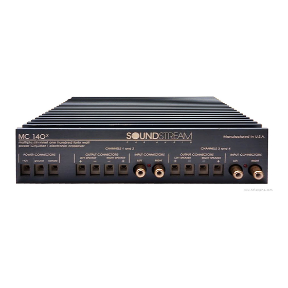
- Page 17 Front Panel Connections MC 140x multiple channel two hundred forty watt amplifier / electronic crossover power POWER CONNECTORS OUTPUT CONNECTORS LEFT SPEAKER ground remote +12V +12v Batterv I ermlnal Bottom Panel Switch Settings Channel 3A fuse 180 Hz 6 dB/Oct high mono pass...
- Page 18 Channels 4and3 AMPLIFIER CONFIGURATION DIAGRAM #9 SOUNDSTREAM’ Manufactured ‘ 4 CHANNELS 3 and INPUT CONNECTORS OUTPUT CONNECTORS INPUT CONNECTOIK LEn SPEAKER RIGHT SPEAKER LEFT RIGHT 180 Hz 4 dB/Oct...
Need help?
Do you have a question about the MC-140X and is the answer not in the manual?
Questions and answers