
Related Manuals for Picotest J2103A


Summary of Contents for Picotest J2103A
- Page 1 J2103A Power Stage Isolator Operation Manual Version 1.0 Dated: 05/14/2023 Copyright© 2023 Picotest®...
-
Page 2: Table Of Contents
2. The package includes ........................3 3. Panel Configuration 1 ........................5 4. Panel Configuration 2 ........................6 5. J2103A Operation Steps ........................7 6. The OSC signal level for J2103A ....................8 7. Specifications ............................ 9 8. Inspection ............................9 Rev 1.0 05142023... -
Page 3: Introduction To J2103A
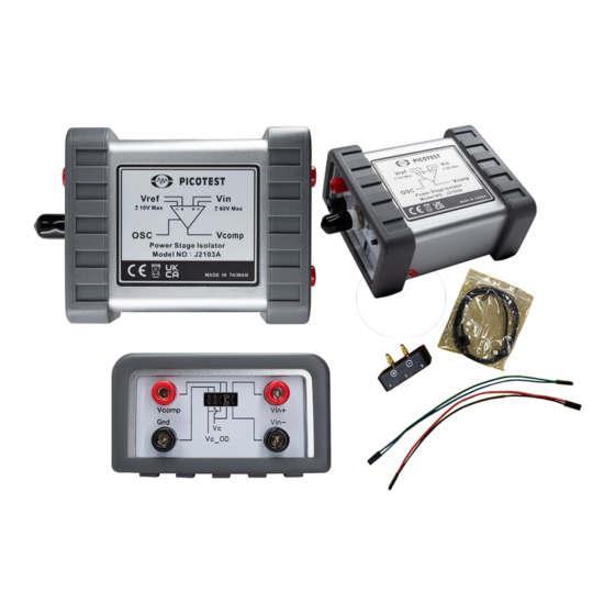
(Power stage) and the feedback control circuit is relatively accurate and greatly shortens the design cycle. The J2103A can be used in almost any power circuit that requires feedback control. Its feedback input (Vin) and reference voltage (Vref) use differential inputs without reference ground problems. - Page 4 J2103A Power Stage Isolator Figure 1 J2103A Product Contents Note 1: For battery transportation, please refer to the lithium battery product transportation regulations in “The shipping regulations for lithium batteries.pdf.” Note 2: For more information on the banana plug to USB adapter, please refer to the PWR-OPT03 user manual in “Banana to USB Connecter1.pdf.”...
-
Page 5: Panel Configuration 1
The configuration diagram of panel 1 for J2103A is shown in Figure 2. Figure 2 J2103A Panel Configuration I According to Figure 2, the J2103A provides two types of input/output ports: Banana jacks and Dupont connectors: a. You can select the Vcomp output using the Dupont terminals. By connecting pin 5 to pin 6 with a jumper capacitor, you can set Vcomp to open drain output. -
Page 6: Panel Configuration 2
J2103A Power Stage Isolator 4. Side Panel Configuration 2 The configuration diagram of panel 2 for the J2103A is shown in Figure 3. Figure 3 J2103A Panel Configuration 2 Figure 3-1 Power Indicator Lights Figure 3-1 shows the Power indicator lights: a. -
Page 7: J2103A Operation Steps
Figure 3-3 USB Type-C Charging Port The USB Type-C charging port shown on Figure 3-3 is for charging only. When J2103A is being charged, the power switch will automatically turn off and cannot be operated. A 5V, 15W USB charger adapter... -
Page 8: The Osc Signal Level For J2103A
There is an OSC to Vcomp port signal attenuation ratio of 20dB. The J2103A operates with a single power supply, and the Vcomp output range is 0~10V. Therefore, the strength of the OSC signal, represented by Vosc/10, must be lower than the DC bias value of Vcomp under no clamp condition. -
Page 9: Specifications
+26dBm, and there is a 20dB attenuation from OSC to Vcomp. The bandwidth is greater than 1MHz. d. Four LTO batteries are connected in series to power the J2103A. They can be fully charged in about 30 minutes and can work continuously for more than 8 hours with Vcomp=10V at no-load and the OSC port not connected. - Page 10 J2103A Power Stage Isolator Figure 8 Frequency response of OSC to Vcomp Rev 1.0 05142023...
Need help?
Do you have a question about the J2103A and is the answer not in the manual?
Questions and answers