
Related Manuals for Picotest J2112A


Summary of Contents for Picotest J2112A
- Page 1 Injectors Documentation Version 2.0, September 2024 Copyright © 2011-2024 Picotest All Rights Reserved...
- Page 2 Substances in Electrical and Electronic Equipment. Information for disposal and recycling The Picotest Probes and Cables and all its accessories are not intended for household use. At the end of its service life, do not dispose of the test set with household waste! For customers in EU countries (incl.
-
Page 3: Table Of Contents
Chapter 2 – Introduction to Signal Injectors ..............9 Introduction ............................9 Injection Transformers – J2100A & J2101A ................10 Solid-State Voltage Injector – J2110A ..................11 Solid-State Current Injectors – J2111B & J2112A ..............13 Line Injectors – J2120A, J2121A, and J2123A ................14 Bias Injector –... - Page 4 J2121A High Power Line Injector ....................33 Main Features ..........................33 Description ..........................33 J2120A – J2121A Injector Comparison ................. 33 Connecting the Line Injector: PSRR ..................34 Technical Specifications ......................34 J2123A Negative Voltage Line Injector ..................36 Main Features ..........................36 Description ..........................
- Page 5 Technical Specifications ......................63 J2113A Semi-Floating Differential Amplifier ................64 Main Features ..........................64 Description ..........................64 Technical Specifications ......................68 J2114A High CMRR Isolation Amplifier ................... 70 Main Features ..........................70 Description ..........................70 Technical Specifications ......................72 J2115A Probe Coaxial Isolator ....................73 Benefits ............................
-
Page 6: Chapter 1 - Overview
Chapter 1 - Overview Welcome Thank you for purchasing one or more of Picotest’s Injectors. The term injector is used to describe a test setup accessory that supports the interconnection between the test instrument and the device under test (DUT). In some cases, the injector might be essential to the test and in other cases, help to improve the measurement fidelity. -
Page 7: Documentation And Support
The support section of Picotest’s web site, https://www.picotest.com/support/injectors/ contains additional documentation and various publications on testing power integrity, power supplies, and other linear and power circuit design using the Picotest Injectors. Warranty Every Picotest product purchased from Picotest.com is backed by a 1-year manufacturer’s warranty. - Page 8 Overview Please note that the absolute maximum voltages ratings are below 400V (DC) for the following Signal Injectors: J2121A. Also, please follow this warning: Please note that the absolute maximum (common mode + differential) voltage rating is below 9.5V (DC+AC) for the J2114A. Please note that the absolute maximum (differential) voltage ratings are below 50V (DC+AC) for the following DC blockers: J2130A.
-
Page 9: Chapter 2 - Introduction To Signal Injectors
Introduction to Signal Injectors Chapter 2 – Introduction to Signal Injectors Introduction Injectors, also known as test adapters or interface adapters, are used to inject or transmit signals into and from various circuits so that the circuit’s characteristics can be tested. Tests include PDN impedance, transient step loading, Bode plot control loop analysis, circuit and component impedance measurements, and conducted susceptibility measurements, to name just a few. -
Page 10: Injection Transformers - J2100A & J2101A
The details can be found in the following sections. The Picotest Injectors may be used with just about any network analyzer including those from OMICRON Lab, Keysight, Copper Mountain, Rohde & Schwarz, Venable, Ridley, and others. -
Page 11: Solid-State Voltage Injector - J2110A
The result is that the incorrect results are invariably produced from the use of these poor injection transformers. Solid-State Voltage Injector – J2110A While it is possible to obtain high quality injection transformers with bandwidths as wide as 1Hz to 5MHz or more, in some cases this is still insufficient for the testing of some circuits. - Page 12 Introduction to Signal Injectors Figure 2: Sample setup for the solid-state injector “Bode Box” (J2110A) used to perform stability measurements. The selection of a valid injection point in the circuit is more critical when using a solid-state injector than with the injection transformer. The solid-state injector presents an infinite impedance between the points of injection.
-
Page 13: Solid-State Current Injectors - J2111B & J2112A
The bias can be disconnected for use with an external waveform or arbitrary waveform generator such as the Picotest G5100A. The current injector is basically a voltage to current converter with a gain of 10mA/V for... -
Page 14: Line Injectors - J2120A, J2121A, And J2123A
Introduction to Signal Injectors into the modulation port and get 10mA out of the output port and 10mV out of the current monitor port. The current injector can be controlled by the output of the network analyzer (for frequency domain sweeps) or a function generator or arbitrary waveform generator (for time domain control and load profiling). - Page 15 Introduction to Signal Injectors Figure 5: Sample setup for the Line Injector (J2121A) used to measure an inductor under DC bias conditions. Figure 6: Sample setup for the Line Injector (J2121A) used to measure the input impedance of a DC-DC converter.
-
Page 16: Bias Injector - J2130A
This is true of semiconductor junction capacitances, varactors, and some ceramic capacitors (especially X5R). In these cases, the impedance is a function of the DC bias on the device. The Picotest DC bias injector (J2130A) is used for this purpose during impedance measurements. -
Page 17: Preamplifier - J2180A And J2180A-20
Introduction to Signal Injectors Preamplifier – J2180A and J2180A-20 The J2180A (and J2180A-20) low noise preamplifiers provide a fixed, AC coupled 20dB gain while converting a 1 MOhm input impedance to a 50 Ohm output impedance. With a 3dB bandwidth of 0.1Hz to 100MHz, the preamplifier improves the sensitivity of oscilloscopes, network analyzers and spectrum analyzers while reducing the effective noise floor and spurious response. -
Page 18: Picotest Family Of Ground Loop Isolators
Introduction to Signal Injectors Picotest Family of Ground Loop Isolators Picotest makes a unique family of ground isolators covering a variety of applications, test setups, and instruments. If there is a ground loop to suppress or eliminate from impacting a measurement, Picotest has the appropriate isolator. -
Page 19: High Cmrr Isolation Amplifier - J2114A
VNAs and oscilloscopes which occur in many different types of test setups. This level of CMRR (highest of all Picotest ground isolators) is necessary to impact the ground loop errors for these impedance levels. If measuring ultra-low impedances is needed, this isolator is essential to the removal of ground loop errors. - Page 20 The adapter can also be combined with ultra-wide bandwidth DC blockers, such as the Picotest Port Saver. This enables 2-port measurements of sensitive devices without the 50 Ohm DC port loading, which could overload the device being measured and/or severely distort the measurement results.
-
Page 21: Chapter 3 - Signal Injectors: Measurements And Specifications
Signal Injectors: Measurements and Specs Chapter 3 - Signal Injectors: Measurements and Specifications J1200A/J2101A Injection Transformers One of the most common tests performed by a network analyzer is the control loop stability measurement or Bode plot. The injection transformer is the most prevalent method for connecting a network analyzer to the circuit in order to perform the stability measurements. -
Page 22: Description
Most other injection transformer manufacturers use an inexpensive ferrite transformer; the price is not indicative of the cost of the transformer. The Picotest injection transformers are made of a specially annealed amorphous material in order to obtain nearly infinite permeability (>100,000). -
Page 23: Connecting The Injection Transformer: Stability
Vout and not ground. In this case the transformer parasitics are much more evident. The Picotest injection transformers are capable of an impressive 23 Octave bandwidth. This bandwidth is still not sufficient to support all requirements, and so two transformers have been designed. -
Page 24: Technical Specifications: J2100A
Signal Injectors: Measurements and Specs Technical Specifications: J2100A Characteristic Rating Conditions 25 degC Ratio Termination 5 Ohms Impedance Nominal 3dB 10Hz - Bandwidth 5MHz 600V Isolation Voltage 3kVrms/1min CATII Isolation Capacitance 150pF 1kHz DC current at which inductance(@1kHz) drops 10% DC current 10mA (typical) from its value without current... -
Page 25: Technical Specifications: J2101A
Signal Injectors: Measurements and Specs Figure 10: Frequency Response for the J2100A and J2101A injection transformer. Technical Specifications: J2101A... - Page 26 Signal Injectors: Measurements and Specs Figure 11: Frequency Response for J2101A injection transformer. Characteristic Rating Conditions 25 degC Ratio Termination 5 Ohms Impedance Nominal 3dB 10Hz - Bandwidth 5MHz 600V Isolation Voltage 3kVrms/1min CATII Isolation Capacitance 150pF 1kHz DC current at which inductance(@1kHz) drops 10% DC current 10mA (typical) from its value without current...
-
Page 27: J2110A Solid-State Voltage Injector
The solid-state voltage injector, or “Bode box”, is employed in the same way as the injection transformer. As noted in the introduction section, the J2110A injector has a wider bandwidth. However, the selection of a point in the circuit to insert the injection connection can be more challenging. -
Page 28: Technical Specifications
Signal Injectors: Measurements and Specs Figure 12: Solid-State Injector Connections for stability measurements. Technical Specifications Characteristic Rating Conditions Max Vs +/-12V 25 degC Max Icc 20mA Max input voltage +/-10.5V DC+AC Output Voltage +/-10.5V Offset Voltage -3dB Bandwidth (-10dBm) DC-100MHz °... -
Page 29: J2120A Line Injector
Signal Injectors: Measurements and Specs J2120A Line Injector Main Features J2120A Line Injector • 10Hz-10MHz usable bandwidth • Low loss design • 5 Amps maximum current • 50VDC maximum input • Easily measure input filters and PSRR Description The line injector allows the input DC supply voltage to be modulated by the network analyzer source signal, as in the case of a PSRR measurement. -
Page 30: Measuring Input Impedance
Signal Injectors: Measurements and Specs Measuring Input Impedance The line injector can also be used in conjunction with a current probe to measure the input impedance of a power supply. The input impedance of a switching power supply or regulator is negative, which is a stability concern when combined with an EMI filter, making the measurement an important part of the design, analysis and verification process. - Page 31 Signal Injectors: Measurements and Specs Connection Note: the black connection is always the return; the red connection is Vin and can be negative (voltage). Note: The J2120A line injector includes an internally biased N-Channel MOSFET. This means that there is a voltage drop between the J2120A input and output. To get an input voltage of 1.2V at the regulator could require 2.5-3.5V depending on the operating current.
- Page 32 Signal Injectors: Measurements and Specs Figure 16: Line Injector output resistance. Characteristic Rating Conditions Maximum DC Input Voltage Maximum Continuous Current Maximum Voltage Drop 3.25V At 5A 3dB Frequency Response 15Hz-5MHz Vin=5V RL=50 Ohms Useable frequency response 10Hz-10MHz Recommended injection signal -20dBm - 0dBm °...
-
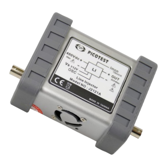
Page 33: J2121A High Power Line Injector
Signal Injectors: Measurements and Specs J2121A High Power Line Injector Main Features J2121A Line Injector • 400V/20A max – Supports High Power 270V Military and Satellite Buss Applications • 100Hz - 1MHz Bandwidth • Regulated Input-Output Voltage Drop, 750mV • Isolated Current Sense Monitor Output (for VNAs only, does not work with oscilloscopes •... -
Page 34: Connecting The Line Injector: Psrr
Signal Injectors: Measurements and Specs • The J2120A favors PSMR and low current, low voltage, PSRR measurement applications • The J2121A has a much higher voltage range, much higher current rating and integrated Hall current monitor, saving the need for an external current probe •... - Page 35 Signal Injectors: Measurements and Specs EMI Note: Exceeding 0dBm may cause the J2120A unit to exceed CE EMI limits. VSS Note: Calibrated Figure 18: The current monitor transfer ratio measurement shows the 100mV/A (-20dB) transfer function from the modulation current to the current monitor output. Uncalibrated, the -3dB frequency is 700kHz.
-
Page 36: J2123A Negative Voltage Line Injector
Signal Injectors: Measurements and Specs J2123A Negative Voltage Line Injector Main Features J2123A Line Injector • Negative voltage line injector • Modulate a DC Power Source Voltage • Combines modulation signal with bus voltage • 10Hz-50MHz usable bandwidth • Low Impedance, Low Noise, and Low Voltage-Compliance •... - Page 37 Signal Injectors: Measurements and Specs Figure 20: the voltage drop of the J2123A is graphically represented above.
-
Page 38: Connecting The Negative Voltage Line Injector: Psrr
Signal Injectors: Measurements and Specs Connecting the Negative Voltage Line Injector: PSRR Figure 21: Line Injector Connections for PSRR measurements. Important Usage Note: The J2123A will be damaged if the input voltage is reversed. In a negative voltage system, the return jack (ground or 0 volts) should be more positive than the MINUS SUPPLY connection. -
Page 39: Technical Specifications
Signal Injectors: Measurements and Specs Figure 22: Internal input capacitor polarity. The line injector is only capable of sourcing current, so that the output amplitude can be significantly impacted by the operating current and the total storage capacitance at the load. The Bode-100 network analyzer has a very high selectivity so distortion at the output of the line injector generally does not influence the measurement. -
Page 40: Technical Specifications
• Bias low power transistor amplifiers and diodes for parameter extraction Description The Picotest DC bias injector (J2130A) is used for applying a DC voltage bias on components during impedance measurements. The J2130A is a Resistor Capacitor Bias Tee which is useful for measuring components, such as capacitors, diodes, small signal BJTs,... -
Page 41: Connecting The Dc Bias Injector: Component Bias
Signal Injectors: Measurements and Specs Connecting the DC Bias Injector: Component Bias Figure 23: Connections for DC Bias Impedance measurements. Technical Specifications Characteristic Rating Conditions Maximum DC Bias 50VDC Bias Resistance 10 kOhms Maximum Bias Current At 50V Frequency Response Frequency Sweep 100Hz-1GHz+ 10Hz~500MHz, Power=-10dBm... - Page 42 Signal Injectors: Measurements and Specs Figure 24: The effect of DC bias on the J2130A frequency performance which shifts the - 3dB frequency.
-
Page 43: J2111B/J2112A Solid-State Current Injector
Signal Injectors: Measurements and Specs J2111B/J2112A Solid-State Current Injector Main Features J2111B & J2112A Solid-State Current Injector • High PSRR Low Noise Regulator with Universal input • 20nSec typical rise and fall time • DC-40MHz usable range (interconnection dependent) • Two Quadrant Bipolar operation works with positive or negative source •... -
Page 44: J2111B Vs. The J2112A
2.5mA. The typical offset in the J2111B is 150uA, and it can be as high as 400uA. It is also possible to use the J2110A in conjunction with the J2111B. The J2111B current injector is capable of SINKING 100mA while the J2112A can SINK up to 1A. -
Page 45: J2111B - J2112A Injector Differences
Signal Injectors: Measurements and Specs • Both injectors can be used in the time domain for step load or load profile testing or in the frequency domain for impedance testing • The output signals of both injectors are driven the same; from either the Bode 100/500 or a voltage source/AWG J2111B –... -
Page 46: 3-Port V/I Impedance Testing
Among various techniques, 3-port impedance testing stands out as a robust method for assessing the characteristics of complex networks and components especially those at elevated voltages (>12V). This article explores how Picotest products, specifically the J2111B Current Injector and Non-Invasive Stability Measurement (NISM) software, combine with a Vector Network Analyzer to provide a comprehensive solution for electronic engineers engaged in 3-port impedance testing. - Page 47 Signal Injectors: Measurements and Specs For an output impedance measurement, connect the output of the current injector using a scope probe (preferably 1X for best sensitivity) from the VNA to the output of the regulator. Connect the scope probe to the “T” input (terminated into 1 MOhm) and the current monitor from the current injector to the “R”...
- Page 48 OFF-state impedance, and lower maximum frequency the 2-port shunt-through is superior in almost every way. If this method is needed, Picotest’s suite of products, including the J2111B Current Injector and NISM software, provides electronic engineers with a powerful and integrated solution for 3-port impedance testing.
-
Page 49: Technical Specifications
Signal Injectors: Measurements and Specs Technical Specifications Characteristic J2111B Rating J2112A Rating Max input voltage DC+AC +/-5V Maximum Output Current +/-74mA Minimum Output Current 24mA Minimum Output Voltage +/- 1.5V +1.5V Absolute Output Voltage -60V to -1.5V and +1.5V to +60V Requirements Current Monitor 1V/A... - Page 50 Signal Injectors: Measurements and Specs Figure 27: J2111A/J2111B frequency response. The J2111A and B have similar responses.
-
Page 51: J2171A High Psrr Regulated Adapter (Power Supply)
• Ultra-high PSRR Description The J2171A power adapter is specially designed for use with the Picotest J2110A, J2111B and other signal injector products. The supply combines a universal worldwide input (100 to 240 VAC) with two high performance linear regulators. -
Page 52: J2140A Attenuators
Signal Injectors: Measurements and Specs J2140A Attenuators Main Features J2140A Attenuator • Integrated unit includes 20dB, 40dB and 60dB • Cascade for greater attenuation • Improve noise floor or assure small signal measurement Description There are two common uses for attenuators when used in conjunction with the network analyzer. - Page 53 Signal Injectors: Measurements and Specs Figure 28: 40dB attenuator frequency response. Figure 29: J2140A S21 and VSWR frequency response.
-
Page 54: J2180A And J2180A-20 0.1Hz To 100Mhz Ultra Low Noise Preamp
Signal Injectors: Measurements and Specs J2180A and J2180A-20 0.1Hz to 100MHz Ultra Low Noise Preamp Main Features J2180A 0.1Hz to 100MHz Ultra Low Noise Preamp • Works with all oscilloscopes, spectrum analyzers and network analyzers • Active DC bias loop maintains low DC output voltage •... -
Page 55: Connecting The Preamp: Emi And Noise Measurements
Signal Injectors: Measurements and Specs Connecting the Preamp: EMI and Noise Measurements Figure 30: Sample setups for the J2180A Preamp used for noise and EMI measurements. -
Page 56: Technical Specifications
Signal Injectors: Measurements and Specs Technical Specifications Characteristic Rating Maximum Vcc +/-12V Maximum Input Voltage 300mVpp Output Voltage 3.0Vpp Maximum Icc 20mA Usable Bandwidth (J2180A) 0.1Hz - 100MHz Usable Bandwidth (J2180A-20) 20Hz - 100MHz ° Temperature range 0-50 Absolute Maximum Voltage <50 VAC and 75VDC Figure 31: Input referred Noise Density 100nV full scale, mid-range noise density is 2nV/Root-Hz. -
Page 57: J2190A 0.1Hz To 10Hz Active Filter
Signal Injectors: Measurements and Specs J2190A 0.1Hz to 10Hz Active Filter Main Features J2190A 0.1Hz to 10Hz Active Filter • 0.1Hz to 10Hz 4 Order Filter • Ultra-low noise • Cascadable with additional filters • Compatible with J2171A power supply Description The J2190A active filter presents a high impedance (approximately 150 kOhms) minimizing the loading of the circuit being tested. - Page 58 Signal Injectors: Measurements and Specs Characteristic Rating Gain 0 dB Noise Input Impedance 1 MOhm Output Impedance 50 Ohms 3dB Bandwidth 0.1Hz – 10Hz Temperature Range 0 – 50C Maximum Altitude 6000 Absolute Maximum Voltage <50 VAC and 75VDC...
-
Page 59: J2102B Common Mode Transformer
DC-DC converters and bulk bypass capacitors. The simplest and most effective solution for eliminating a ground loop is to add a wideband common mode transformer to the measurement, such as the Picotest J2102B Common Mode Transformer. The transformer for a low impedance PDN measurement must have very wide bandwidth, low loss and tight coupling;... - Page 60 Signal Injectors: Measurements and Specs Figure 34: Electrical connection diagram showing the placement of the J2102B and Port Saver DC blockers for a 2-port shunt impedance measurement. Figure 35: Common Mode Frequency response of the J2102B.
- Page 61 Signal Injectors: Measurements and Specs Figure 36: Impedance measurement of a 1mΩ resistor with and without the J2102B common mode transformer using the Copper Mountain S5065 VNA. Figure 37: Impedance measurement of a 1mΩ resistor with and without the J2102B common mode transformer using the Rohde &...
- Page 62 Signal Injectors: Measurements and Specs Figure 38: J2102B Return Loss Graph. Figure 39: J2102B Insertion Loss Graph.
-
Page 63: Technical Specifications
Signal Injectors: Measurements and Specs Technical Specifications Characteristic Rating 3dB Bandwidth 1Hz-6GHz Insertion Loss Return Loss Maximum Voltage Temperature Range 0-50C Maximum Altitude 6000 Ft Absolute Maximum Voltage < 50VAC and 75VDC... -
Page 64: J2113A Semi-Floating Differential Amplifier
Design assurance, optimization and troubleshooting all require accurate low impedance measurements. Whether modeling components, testing power supply output impedance, assessing target impedance, or looking to manage PDN resonances, Picotest has a 2-port testing solution available. And the J2113A is essential to removing the ground loops associated with VNAs and Oscilloscopes which occur in many different types of test setups. - Page 65 J2113A differential amplifier. This is the test setup for the measurement of most types of passive components. Figure 41: Measuring a low value resistor using Picotest Decoupling Boards in a 2-port configuration. PDN Cable helps minimize measurement errors.
- Page 66 Amplifier and with no ground loop breaker at all. The reduction in the error of the measurement is clearly seen. Shown below is the Picotest P2102A 2-Port Probe. With its multiple head options, browsing multiple board connections to make the 2-port measurement is easy.
- Page 67 Signal Injectors: Measurements and Specs Two Picotest P2105A 1-Port probes can also be used. This will provide more flexibility with connection pitch and the ability to probe both sides of a PCB. Figure 44: Test setup for measuring the in-circuit output impedance using two 1-Port PDN Probes (P2105A).
-
Page 68: Technical Specifications
Signal Injectors: Measurements and Specs Figure 46: 2-Port shunt-through impedance measurement results using two 1-Port PDN Probes. Technical Specifications Characteristic Rating Typical Bandwidth DC-800 MHz (-3dB), DC-700MHz (-1dB) Maximum Voltage 1.9V CMRR (Typical) 57dB Temperature range 0-50C Maximum Altitude 6000 Ft Absolute Maximum Input Voltage is +/- 2V... - Page 69 Signal Injectors: Measurements and Specs Figure 47: S21, S11, and S22 plots show 3dB S21 -3dB bandwidth @ 830MHz and S22 -6dB bandwidth @ 635 MHz. Figure 48: J2113A Linearity Graph.
-
Page 70: J2114A High Cmrr Isolation Amplifier
Signal Injectors: Measurements and Specs J2114A High CMRR Isolation Amplifier Main Features • Eliminates DC ground loop down to DC • Supports the 2-port shunt-through impedance measurement required for Power Distribution Networks (PDNs) • Enables measurement of ultra-low (micro-Ohm) impedances •... - Page 71 Signal Injectors: Measurements and Specs Figure 50: The J2114A is powered by a USB connection and comes with PDN Cable. Figure 51: Frequency response of the Common Mode Rejection for the J2113A and J2114A shows how much more CMRR the J2114A possesses, necessary for ultra-low impedance testing.
-
Page 72: Technical Specifications
Signal Injectors: Measurements and Specs Figure 52: 2-port impedance measurement with the P2102A probe, J2114A, and the Bode 500 VNA. Technical Specifications Characteristic Rating Recommended Bandwidth DC-10 MHz Maximum Voltage Common mode + differential is 9.5V max Maximum Voltage Differential Differential mode is 7.07 Vrms max 9.5Vpk CMRR... -
Page 73: J2115A Probe Coaxial Isolator
Analyzers, Oscilloscopes and Spectrum Analyzers Description The Picotest Probe Coaxial Isolator is a common mode transformer that minimizes the ground loop in power rail and other forms of voltage probe measurements that exist in all oscilloscopes, and other instrument setups. -
Page 74: Technical Specifications
Signal Injectors: Measurements and Specs 1. Reduce the ground connection impedance using low shield resistance cable such as PDN cable 2. Make at least the most sensitive channel connection as short as possible 3. Add common mode isolators. This is the most effective solution. Figure 53: J2115A performance for CMRR, insertion loss, DC bias, and return loss. -
Page 75: J2161A Active 2-Way Splitter
Description Perform the “Gold Standard” PDN measurement on the Tektronix Series 6 oscilloscope: the 2-port shunt-through impedance measurement is enabled by the Picotest J2161A active splitter, along with either a J2102B or a J2113A differential amplifier (for ground loop breaking). The combination allows measurement of low impedances over frequency down to... - Page 76 Signal Injectors: Measurements and Specs Figure 54: – 2-port shunt-through impedance test setup using the Tektronix Series 6 scope, J2161A, and the J2102B.
- Page 77 Signal Injectors: Measurements and Specs Figure 55: – Tektronix Series 6 test setup to perform the 2-port shunt-through impedance measurement using the Picotest J2161A active splitter (left) and the J2102B common mode transformer (right). Figure 56: 2-Port Shunt-Through Impedance measurement of a 1 mOhm (1.17m) resistor.
- Page 78 Signal Injectors: Measurements and Specs Figure 57: 2-Port Shunt-Through Impedance measurement of a 100uF polymer capacitor. Figure 58: 2-Port Shunt-Through Impedance measurement of a 3.3uH inductor.
-
Page 79: Technical Specifications
Signal Injectors: Measurements and Specs Technical Specifications Specifications Characteristic Rating Uncalibrated Insertion Loss < 100MHz 1dB >100MHz - 500MHz 3dB Input Return Loss (typical) < 100MHz < -20dB >100MHz - 500MHz 12dB Output Return Loss (typical) < 100MHz < -20dB >100MHz - 500MHz 12dB Gain Out to Out Isolation... - Page 80 Signal Injectors: Measurements and Specs Figure 59: S21, S11, and S22 plots show 3dB S21 -3dB bandwidth @ 830MHz and S22 -6dB bandwidth @ 635 MHz.
- Page 81 Signal Injectors: Measurements and Specs Figure 60: J2161A Typical measured frequency response data.
- Page 82 Signal Injectors: Measurements and Specs Figure 61: J2161A Typical Noise Density plot.
-
Page 83: J2160A 2-Port Probe Adapter Panel For The Keysight E5061B
• Works with the J2130A DC Bias Source Description The Picotest J2160A Probe Adapter provides a low noise, easy to connect and compact solution when using the E5061B T/R ports in a 2-port shunt-through measurement; the main measurement used in component and Power Integrity/PDN impedance measurements. - Page 84 Signal Injectors: Measurements and Specs Using the Picotest J2160A shown below, connect the three GP Ports on the Keysight E5061B. This configures the ports for the 2-Port Shunt-Through measurement at low frequencies. Figure 63: Measuring Components Using the Keysight E5061B GP Ports (Low Frequency).
- Page 85 Signal Injectors: Measurements and Specs Figure 64: 10 milli-Ohm Resistor measurement using the Keysight E5061B VNA GP Ports and the Picotest J2160 adapter.
- Page 86 Signal Injectors: Measurements and Specs Figure 65: The 6dB splitter is accurate to within 0.25dB across the full frequency range of the instrument.
- Page 87 Signal Injectors: Measurements and Specs Figure 66: The T port return loss is better than 30dB over the full frequency range of the instrument.
- Page 88 Signal Injectors: Measurements and Specs Figure 67: The T port insertion loss is less than a few hundredths of a dB over the full instrument range.
- Page 89 Signal Injectors: Measurements and Specs Figure 68: The return loss of the 6dB splitter legs is better than 25dB over the full measurement range of the instrument.
-
Page 90: Injector Input/Output Impedances
Signal Injectors: Measurements and Specs Injector Input/Output Impedances J2110A Impedance Modulation Input 50 Ohms Output 25 Ohms Input High Z J2111B Modulation Input 50 Ohms Current Monitor Output 50 Ohms J2120A Modulation Input 10K Ohms J2121A Modulation Input 50 Ohms...
Need help?
Do you have a question about the J2112A and is the answer not in the manual?
Questions and answers