Table of Contents
Advertisement
Advertisement
Table of Contents

Related Manuals for Fuji Electric AF-300 C11


Summary of Contents for Fuji Electric AF-300 C11
- Page 1 AF-300 C11 User’s Guide Get other manuals https://www.bkmanuals.com...
-
Page 2: Table Of Contents
TABLE OF CONTENTS BEFORE USING THIS PRODUCT ..11 MAINTENANCE AND INSPECTION .70 ....11 ......70 ECEIVING NSPECTIONS AILY NSPECTION ........12 ...... 70 PPEARANCE ERIODIC NSPECTION ....13 ANDLING THE RODUCT LECTRICAL MEASUREMENTS IN THE ........14 ......... 73 ARRYING IRCUIT .. - Page 3 Safety Instructions Read this operation manual carefully and familiarize yourself with the operation of the drive be- fore installation, connection (wiring), operation or maintenance and inspection of the device. Be familiar with the drive, safety information, and safety signs before using the drive. In this instruction manual, safety signs are classified into the following categories.
- Page 4 Compliance with low voltage directive in EU [Applicable to products with TÜV mark] CAUTION 1. Safe separation for control interface of this drive is provided when this drive is installed in overvoltage category II. PELV(Protective Extra Low Voltage) circuit or SELV(Safety Extra Low Voltage) circuit from external controller is connected to the interface directly.
- Page 5 Compliance with low voltage directive in EU [Continued] CAUTION Use of wires specified in Appendix C of EN 60204 is recommended. Recommended wire size AWG (mm Molded case circuit Input circuit breaker (MCCB) or Power 3-phase 200V Nominal earth leakage cir- supply applied [L1/R, L2/S, L3/T],...
- Page 6 Instructions on use WARNING 1. This drive is designed to drive a three-phase induction motor and is not usable for a single- phase motor or any other purposes. There is a risk of fire 2. This drive may not be used as is for an elevator, life-support system, or other purpose directly affecting the safety of humans.
- Page 7 Instructions on wiring WARNING 1. When the drive is connected to power, connect it via a line-protection molded case circuit breaker or an earth-leakage circuit breaker (Residual current operated protective device). Otherwise, fire could occur. 2. Be sure to connect the ground wire, otherwise electric shock or fire could occur.
- Page 8 Instructions on operation WARNING 1. Be sure to put on the surface cover before turning the power ON (close). Never remove the cover while the power is applied to the drive. Otherwise electric shock could occur. 2. Never operate switches with wet fingers. Otherwise electric shock could occur.
- Page 9 Instruction on maintenance/inspection, and replacement WARNING 1. Do not commence inspection work until at least five minutes after the power has been turned off (open). (In addition, make sure that the charge lamp has gone off and check that the DC voltage between terminals P(+) and N(-) does not exceed 25V DC.) Otherwise electric shock could occur.
- Page 10 Preface Thank you for purchasing our AF-300C11 series drive. This product is used to drive a 3phase electrical motor at variable speed. Incorrect use of this product may result in personal injury and/or property damage. Read all operating instructions before using this device. Since this manual does not cover the use of option boards, etc., refer to relevant manuals for option operations.
- Page 11 AF-300C11 Model Numbering System Diagram Description 6K C11 (X/N)NN GE Product Code AF-300 Drive Family Input Voltage 2 = 230V 50/60 Hz Input Phases 1 = Single Phase 3 = 3 Phase Horsepower F50 = 1/2 Hp 001=1 Hp Factory Installed Options X= Keypad Enclosure Type 1=IP20...
- Page 12 AF-300C11 Rated Output Overload Dimensions Current (150% AF-300C11 H x W x D Weight HP Rating Enclosure 1min.) Model No. Catalog No. (inches) (lbs) 230VAC, 3 phase, 50/60Hz Input IP20 6KC1123F12X1 * * D5674 4.72 x 3.15 x 3.23 IP20 6KC1123F25X1 * * D5675 4.72 x 3.15 x 3.43...
-
Page 13: Before Using This Product
1 Before Using This Product Receiving Inspections Unpack and check the product as explained below. If you have any questions or problems with this product, please contact GE FUJI Drives or your local GE distributor. (1) Check the ratings name plate to confirm that the delivered product is the ordered one. Figure1-1-1 Ratings nameplate ¬... -
Page 14: Appearance
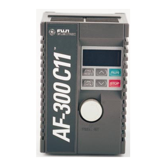
Appearance (1) Surface cover (2) Keypad panel (3) Frequency setting POT (VR) (built-in POT) (4) Ratings nameplate (5) Heat sink (6) Cooling fan (2 HP or more) (7) Charge lamp CRG (8) Control terminal block (9) Main circuit terminal block 3-phase230V[ G,L1/R,L2/S,L3/T,P1,P(+)] Single-phase 230V [ G,L1/L,L2/N,P1,P(+)] (10) Main circuit terminal block... -
Page 15: Handling The Product
Handling the Product Remove the surface cover as explained below. (1) For 1/8 to 1 HP Grasp the upper and lower parts of the cover with both hands and pull it to the front of the drive. (2) For 2 to 5 HP Expand the lower part of the cover horizontally, lift the cover to the front, and then remove it. -
Page 16: Carrying
Carrying Always hold the main unit while carrying this product. If it is carried by the cover or parts and not the main unit, the product may be damaged or dropped. Force must not be applied to the drive cover during carrying because it is made of plastic. Storage and transportation Store and transportation this product under the conditions listed in Table 1-5-1. -
Page 17: Installation And Connection15
2 Installation and Connection Operating Environment Install this product at a place satisfying the conditions listed in Table 2-1-1. Table 2-1-1 Operating environment Item Specifications Place Indoor Ambient -10 to +50 °C (+14 to +122°F) temperature Ambient relative 5 to 95%RH(No condensation allowed) humidity The product must not be exposed to dust, direct sunlight, corro- sive gas, inflammable gas, oil mist, vapor, or water drops. -
Page 18: Connection
° If two or more drives need to be installed in the same device or control panel, they should be ar- ranged horizontally to minimize the influence of heat between them. If two or more drives must be installed vertically, place a plate between them to prevent the upper drive from being affected by heat from the lower drive. -
Page 19: Connecting The Main Circuit And Ground Terminals
2-3-2 Connecting the main circuit and ground terminals Table 2-3-1 Functions of main circuit and ground terminals Symbol Name Explanation Connects 3-phase power.(3-phase 230V input) L1/R,L2/S,L3/T Main power supply input Connects single-phase power. (Single-phase 230V input) L1/L,L2/N U, V, W Drive output Connects 3-phase motor. -
Page 20: Connecting The Control Terminals
(3) DC reactor connecting terminal [P1, P(+)] Use this terminal to connect a input power-factor correcting DC reactor (optional). Remove the jumper connected in the factory before connecting the DC reactor (see Figure 2-3-2). P(+) Use diagonal cutting pliers to cut the surface cover barriers AF-300C11 from P1, P(+) terminals before connection. - Page 21 (2) Run/stop command terminal (FWD, REV) FWD terminal is short-circuit to CM terminal in the factory. Pressing the RUN key on the keypad panel can start forward operation. If function F02 is 0, short-circuit FWD and CM and press the RUN key for forward operation, or short-circuit REV and CM for reverse operation.
- Page 22 Noise is generated from the drive, motor, and wiring. Take care that CAUTION this noise does not cause malfunctions in peripheral sensors and equipment, otherwise accidents could occur. (4) Control terminal arrangement, screw size, and tightening torque Figure 2-3-7 shows the control terminal block arrangement. Screw size: M2.5 Tightening torque: 3.5 lb ·inch ( 0.4 N·...
- Page 23 Table 2-3-2 Functions of control circuit terminals Termi- Classifi- Terminal name Detailed specifications Remarks cation symbol Power supply for Used as power supply for frequency setting variable resistor device (POT: 1 to 5 kΩ). (+10Vdc 10mA max.) Frequency setting 0 to +10Vdc /0 to 100%,0 to +5Vdc /0 to voltage input 100% Analog...
- Page 24 Termi- Classifi- Terminal name Detailed specifications Remarks cation symbol FM, 11 Analog monitor Data selected between the following items is output with DC voltage: Output frequency PID feedback value Output current DC link circuit voltage Analog * Up to two analog voltmeters (input imped- output ance : 10 kΩ...
-
Page 25: Connection Examples
2-3-4 Connection examples 1) Keypad panel operation When power-factor correcting DC reactor is used P(+) P(+) P(+) N(-) MCCB Fuse 3-phase L1/R 230V input series L2/S 200 to 230V 50/60Hz L3/T MCCB Fuse Single-phase L1/L RESET 230V input series FUNC STOP 200 to 240V DATA... - Page 26 2) External operation When power-factor correcting DC reactor is used P(+) P(+) P(+) N(-) MCCB 3-phase L1/R 230V input series L2/S 200 to 230V 50/60Hz L3/T MCCB Fuse Single-phase RESET L1/L 200V input series FUNC STOP 200 to 240V DATA 50/60Hz L2/N Frequency setting POT (VR)
- Page 27 3) Connection to PLC (when external thermal O/L relay is used) MCCB P(+) P(+) N(-) External thermal O/L relay FUSE L1/R 3-phase 230V input series L2/S 200 to 230V L3/T 50/60Hz To X2 To X2 To CM terminal To CM terminal terminal terminal MCCB...
- Page 28 4) Connection to PLC (when analog signal is input from PLC) FUSE P(+) P(+) N(-) MCCB External thermal relay L1/R 3-phase 230V L2/S input series 200 to 230V L3/T 50/60Hz To X2 terminal To CM terminal MCCB FUSE Single-phase L1/L RESET 230V input series FUNC...
-
Page 29: Others
Others 2-4-1 Harmonic component A harmonic component which may influence the phase-advance capacitor and generator is included in the drive input current. If necessary , connect a power-factor correcting DC reactor (DCR) (option) for the drive. 2-4-2 Noise When noise generated from the drive may affect peripheral equipment, and noise generated from pe- ripheral equipment may malfunction the drive, the following basic countermeasures should be taken. -
Page 30: Operation
Operation Inspection and Preparation before Operation Check the following before operation: (1) Check whether the connection is correct, For 3-phase 230V series, check whether the power supply is connected correctly to the L1/R, L2/S and L3/T terminals. For single-phase 230V series, check whether the power supply is con- nected correctly to the L1/L and L2/N terminals. -
Page 31: Trial Run
Trial Run The motor rotates when a frequency value and running command are input from the keypad panel or external signal terminal. Refer to Table 3-3-1. Use a low frequency (about 5Hz) for trial runs A frequency can be set using the built-in frequency setting POT (VR) , and forward/stop can be performed using the keypad panel with the functions set in the factory. -
Page 32: Keypad Panel
1. The STOP key is valid only when the function has been set. Assign another switch to emergency stops, otherwise accidents could occur. WARNING 2. Operation starts suddenly if alarm reset is done with an running signal input. Check that no running signal is input before alarm reset, otherwise accidents could occur. -
Page 33: Operating Keypadp
Operating Keypad Panel 1) Switching monitor The display can be switched between frequency display and output current display by pressing FUNC in Operation mode. DATA *1 Frequency is displayed as a percentage with the least significant digit in PID control operation FUNC FUNC FUNC... - Page 34 Procedure Display Press the key to set the program mode. 6 0. 0 RESET F 0 0 Press the key to select a function. F 0 1 FUNC Press the key to display data. DATA Press the key to change the data. FUNC F 0 2 Press the...
-
Page 35: Selecting Function
FUNC Change during operation: N = impossible, Y* = possible (enabled by using ), Y = possible (enabled by using DATA Selecting Function Function Selection List Function Selection List Table 5-1-1 Table of F: Fundamental functions Func- Change Factory tion Min. - Page 36 FUNC Change during operation: N = impossible, Y* = possible (enabled by using ), Y = possible (enabled by using DATA Func- Change Factory tion Min. User Name Setting range Unit during setting code unit setting operation Electronic thermal 0:Inactive overload relay (Select) 1:Active (for 4-pole standard motor)
- Page 37 FUNC Change during operation: N = impossible, Y* = possible (enabled by using ), Y = possible (enabled by using DATA E: Extension Terminal Functions Func- Change Factory tion Min. User Name Setting range Unit during setting code unit setting operation X1 terminal function Use the code values listed below to se-...
- Page 38 FUNC Change during operation: N = impossible, Y* = possible (enabled by using ), Y = possible (enabled by using DATA P: Motor Parameters Func- Change Factory tion Min. User Name Setting range Unit during setting code unit setting operation Motor characteristics 0 to 10 H: High Performance Functions...
- Page 39 FUNC Change during operation: N = impossible, Y* = possible (enabled by using ), Y = possible (enabled by using DATA O: Optional Functions Change Function Min. Factory User Name Setting range Unit during code No. unit setting setting operation RTU Option 0 : Inactive 1 : Active Address...
-
Page 40: Details Of Eachf
FUNC Change during operation: N = impossible, Y* = possible (enabled by using ), Y = possible (enabled by using DATA Details of Each Function Change during Factory Data protection operation setting Set data can be locked to prevent it from being changed by mistake when using the keypad panel: Data can be changed. - Page 41 FUNC Change during operation: N = impossible, Y* = possible (enabled by using ), Y = possible (enabled by using DATA Operation method Change during Factory operation setting The following four values can be selected: Keypad operation [ RUN STOP The motor runs when the key is pressed and decelerates-to-stop when the key is...
- Page 42 FUNC Change during operation: N = impossible, Y* = possible (enabled by using ), Y = possible (enabled by using DATA GE START SOFTWARE SELECTION DURING TERMINAL OPERATION Inactive : Setting 1 or 2 Active : Setting 3 or 4 POWER ON POWER POWER...
- Page 43 FUNC Change during operation: N = impossible, Y* = possible (enabled by using ), Y = possible (enabled by using DATA Change during Factory Maximum output frequency operation setting 60Hz This function sets the maximum output frequency. The maximum output frequency can be set with a resolution of 1 Hz in a range between 50 and 120 Hz.
- Page 44 FUNC Change during operation: N = impossible, Y* = possible (enabled by using ), Y = possible (enabled by using DATA Change during Factory Base frequency operation setting 60Hz This function sets a base frequency (branch point between constant torque characteristic and constant output characteristic).
- Page 45 FUNC Change during operation: N = impossible, Y* = possible (enabled by using ), Y = possible (enabled by using DATA Change during Factory Torque boost operation setting This function can choose between 32 types of boost according to the load type and motor characteris- tics.
- Page 46 FUNC Change during operation: N = impossible, Y* = possible (enabled by using ), Y = possible (enabled by using DATA Factory Change during Electronic thermal O/L relay (thermal time constant) operation setting 5.0min 0. 5 This function sets the operating time of the electronic thermal O/L relay when the current that is 150% of the operation level flows.
- Page 47 FUNC Change during operation: N = impossible, Y* = possible (enabled by using ), Y = possible (enabled by using DATA Continued from previous page Operating time characteristics “ ® ? ì? ? Œ À “ Á (Base frequency) 1 Hz 5 Hz 2 0 Hz 3 0 Hz...
- Page 48 FUNC Change during operation: N = impossible, Y* = possible (enabled by using ), Y = possible (enabled by using DATA Factory Change during setting Operation F14 Restart mode after momentary power failure This function determines whether operation is restarted upon recovery from momentary power failure: Inactive Failure while drive is stopped: The stop status is continued after recovery from the failure.
- Page 49 FUNC Change during operation: N = impossible, Y* = possible (enabled by using ), Y = possible (enabled by using DATA Factory Change during setting operation Gain (for frequency setting signal) This function outputs the frequency obtained by multiplying the reference frequency by a ratio. This function selects an analog input signal level with a value from 1 to 4 that is set by function F 0 1 .
- Page 50 FUNC Change during operation: N = impossible, Y* = possible (enabled by using ), Y = possible (enabled by using DATA Factory Change during DC injection brake setting operation (starting frequency) 3.0Hz This function sets 3.0Hz (fixed) as the starting frequency of DC injection brake. Factory Change during setting...
- Page 51 FUNC Change during operation: N = impossible, Y* = possible (enabled by using ), Y = possible (enabled by using DATA Factory Change during Starting frequency setting Operation Stop frequency Starting frequency stop frequency These functions set a starting or stop frequency in a range from 1 to 6Hz in 1Hz step.
- Page 52 FUNC Change during operation: N = impossible, Y* = possible (enabled by using ), Y = possible (enabled by using DATA Factory Change during sound Motor setting operation (sound tone) This function adjusts the motor operation sound when a value of 7 or less is set with function F26. Level 0 Level 3 Factory...
- Page 53 FUNC Change during operation: N = impossible, Y* = possible (enabled by using ), Y = possible (enabled by using DATA Factory Change during setting operation 30Ry operation mode This function sets the operation mode of alarm output for any fault (30Ry). Normal Tripped operation...
- Page 54 FUNC Change during operation: N = impossible, Y* = possible (enabled by using ), Y = possible (enabled by using DATA Factory Change during setting operation X1 terminal function X2 terminal function X3 terminal function Multistep frequency selection 1 (SS1) Multistep frequency selection 2 (SS2) Output Frequency selected with F01...
- Page 55 FUNC Change during operation: N = impossible, Y* = possible (enabled by using ), Y = possible (enabled by using DATA Continued from previous page Link operation selection (LE) Operation setting can be done by commands from RS485 when the LE terminal is connected to the CM terminal.
- Page 56 FUNC Change during operation: N = impossible, Y* = possible (enabled by using ), Y = possible (enabled by using DATA Factory Change during setting operation 0.0Hz Jump frequency 1, 2, 3 0.0Hz 0.0Hz These functions jump frequencies to prevent overlap be- tween the load mechanical resonance point and drive Output Frequency output frequency.
- Page 57 FUNC Change during operation: N = impossible, Y* = possible (enabled by using ), Y = possible (enabled by using DATA Factory Change during setting Operation time operation Monitoring only. This function displays the integration time of power supply applied to the drive. 0 to 655 are displayed to indicate 0 to 65500 hours.
- Page 58 FUNC Change during operation: N = impossible, Y* = possible (enabled by using ), Y = possible (enabled by using DATA Factory Change during Data initialization setting operation This function initializes data items set with all functions to values set in the factory. Manually set value Initialized (factory set value ) The display is changed from...
- Page 59 FUNC Change during operation: N = impossible, Y* = possible (enabled by using ), Y = possible (enabled by using DATA Factory Change during PID control setting operation (Feedback signal) This function selects a PID control feedback signal. 0 Terminal 12 (0 to +10Vdc) 1 Terminal C1 (4 to 20mAdc)
- Page 60 FUNC Change during operation: N = impossible, Y* = possible (enabled by using ), Y = possible (enabled by using DATA PID control In PID control, an output frequency is adjusted to a feedback value. to set a frequency and to make the feedback value and the refer- F 0 1 H 2 1...
-
Page 61: Protective Function
Protective Function List of protective functions When the protective function is activated, drive output is instantly cut off (while the motor coasts until it is stopped), and an alarm is issued, and the details of the alarm are displayed on the keypad panel. Table 6-1-1 List of Protective Functions Keypad panel dis-... -
Page 62: Alarm Reset
Keypad panel dis- Alarm Name Contents of operation play Memory Error If memory error occurs, such as a missing or invalid data, output is shut down, an alarm is issued , and the drive is tripped. CPU Error If CPU error occurs because of noise, etc., output is shut down, an alarm is issued, and the drive is tripped. -
Page 63: Troubleshooting
Troubleshooting In case of tripping In the event the drive tripping, diagnose by the help of the alarm display as shown below. (1) Overcurrent (OC) Overcurrent dur- Overcurrent during Overcurrent while run- acceleration ning at constant speed deceleration OC2 Are the motor connecting terminal (U,V,W) short-circuited or Remove short-circuit grounded? or ground. - Page 64 (2) Overvoltage(OU) Fix supply voltage to Overvoltage during Overvoltage during Overvoltage while within upper limit of acceleration running at constant deceleration OU2 specifications. speed OU3 If caused by momen- tary voltage surge Power supply voltage within specified value? from power supply, consider installing a power-factor correct- ing DC reactor.
- Page 65 (3) Undervoltage(LU) (4)Overheating of heat sink (OH1) Heat sink overheat- ing (OH1) Has (momentary) power fail- Reset and restart opera- ure occurred? tion. (If F14 is 0,1) Load excessive? Reduce load. Replace faulty parts and Faulty parts or loose connec- tion in power control circuit? fix connection.
- Page 66 (6) Drive overload (OLU) or motor overload (OL) Connect thermal O/L Do characteristics of elec- tronic thermal O/L relay relay externally. and those of motor over- load match? Is electronic thermal O/L Set to correct level. relay setting correct? Probable faulty drive or Load excessive?.
- Page 67 (7) Memory error (Er1) CPU error (Er3) Abnormal dis- Memory error CPU error Analog frequency set to play or indica- Er 1 Er 3 negative value? tion goes out Reset analog frequency to Turn power OFF then ON positive value. again after CHARGE lamp has gone out.
- Page 68 (9) Input phase failure (Lin) and imbalance Are all the three phases of the Connect the input wires correctly. input voltage supplied? Is the inter-phase imbalance ratio Examine the power supply system within 2%? to satisfy the specification value. Probable faulty drive. Contact GE Fuji.
-
Page 69: Other Trouble
Other trouble When motor does not rotate. Note : Verify the function settings for the operation com- mands and frequency setting values on the keypad panel. Motor does not Are circuit breaker and Investigate cause of start. magnetic contactor on failed switching, and power supply side turn them ON if there is... - Page 70 The motor does not rotate if the following commands are given. 1) An operation command is given while coast-to-stop command is output to the control terminals. 2) Both operation command FWD and REV are input. (2) When motor rotates but the speed does not change. Motor rotates but speed does not change.
- Page 71 (3) When motor stalls during acceleration Motor stalls during accel- eration Acceleration time setting Prolong time setting. too short? Moment of inertia of motor Special motor in use? Consult with GE Fuji.. or load excessive? Reduce moment of inertia Motor terminal voltage of load or increase drive Use thicker cable for wir- lowered?
-
Page 72: Maintenance And Inspection
Maintenance and Inspection Execute the daily inspection and periodic inspection for preventing a fault and ensuring long-term reliability. Note the following regarding the work. Daily Inspection During the operation and conduction, the visual inspection for abnormal operation is executed from the outside without removing the covers. - Page 73 Table 8-2-1 Periodic inspection list Check part Check item How to inspect Evaluation criteria 1) Check the ambient air tem- 1) Measure by visual 1) The specified standard Environment perature, humidity, vibration, inspection and the value must be satisfied. 2) No foreign matter or atmosphere (dust, gas oil mist, meter.
- Page 74 Check part Check item How to inspect Evaluation criteria Resistor 1)Unpleasant smell and crazing 1)Olfactory and 1)Not abnormal. of the insulation by visual inspection 2)Less than about ±10% of overheating 2)Visual inspection the indicated 2)No open circuit? or use a multimeter resistance value by removing a connection on one...
-
Page 75: Electrical Measurements In The Main Circuit
Electrical measurements in the Main Circuit The indicated values depend on the meter types because of harmonic components included in the voltage and current of the main power supply (input) and the output (motor) side of the drive. Therefore, when measuring with a meter for the commercial power frequency, use the meters shown in Table 8-3-1. -
Page 76: Insulation Test
[In the case of 3-phase input series] [In the case of single -phase input series] – N(–) P(+) L1/R Motor L1/L L2/S L2/N L3/T – Figure 8-3-1 Diagram for connections of meters Insulation Test As much as possible, do not test the drive with a megger because an insulation test was done at shipping from the factory. -
Page 77: Inquiries About Products And Product Warranty
(2) Insulation test in the control circuit The megger test and the dielectric strength test must not be executed in the control circuit because those parts will be damaged and cannot be repaired. Use a high-resistance multimeter for the control circuit. 1 Remove all external wiring from the control circuit terminals. -
Page 78: Warranty Service
Warranty Service The purpose of the following section is to provide Before calling the number at left to determine specific instructions to the user of the AF-300C11 warranty status, the drive serial number will be drive regarding warranty administration and how required. - Page 79 IN-WARRANTY FAILURE CHECKLIST To assist with warranty troubleshooting, the following information is required. This data is needed to evaluate the cause in an effort to eliminate any further failures. Model No.:_____________________________________________________________ Serial No.:____________________________________________________________ Start-Up Date:_________________________________________________________ Failure Date:__________________________________________________________ Status When Failure Occurred (check one): Power-Up___________ Running____________ Accel__________ Decel__________ Explanation of Failure ________________________________________________ Application Information (check Yes or No)
-
Page 80: Specifications
Specifications Standard Specifications 1) Three-phase 230V input Item Specifications Drive HP Nominal applied motor *1 (HP) Rated output 0.28 0.56 capacity *2 (kVA) Voltage(V) 3-phase, 200V/50Hz, 200, 220, 230V/60Hz (Proportional to input voltage) Rated current (A) 10.0 16.5 • Overload capacity 150% of rated current for 1 min. - Page 81 2) Single-phase 200V input series Item Specifications Drive HP Nominal applied motor *1 (HP) Rated output 0.28 0.56 capacity *2 (kVA) • Voltage(V) 3-phase, 200V/50Hz, 200, 220, 230V/60Hz (Proportional to input voltage) Rated current (A) 10.0 • Overload capacity 150% of rated current for 1 min. •...
-
Page 82: Common Specifications
Common specifications Item Specifications Remarks Maximum • output fre- 50 to 120Hz (in 1Hz steps) quency Base • 25 to 120Hz (in 1Hz steps) frequency Starting fre- • 1 to 6Hz (in 1Hz steps) quency Carrier fre- • 0.75 to 15kHz quency (Vector-distribution PWM control selectable at 7kHz or less) When operating at a carrie r frequency of 9kHz or above, the frequency... - Page 83 Item Specifications Remarks • Frequency jump Jump frequency (3 points) and jump hysteresis width (1 point) can be pre- control set. Restart after • momentary Drive restarts without causing drive-trip when power supply recovers. power failure • PID control PID control function is provided standard. •...
- Page 84 Item Specifications Remarks • Overload Internal electronic thermal overload relay protects drive overload. • Overvoltage Detect the excessive DC link circuit voltage to stop drive. • Overcurrent Detect overcurrent due to overload on drive output side to protect drive • Incoming surge Detect incoming surge voltage between AC power and the earth to protect drive.
- Page 85 Item Specifications Remarks • Installation Indoor use only. Do not install a dusty location(Degree of pollution: 2) or location expose to direct sunlight, corrosive gases, flammable gases. • Ambient -10 to +50°C (+14 to +122°F ) temperature • Ambient 5 to 95%RH ( No condensation ) humidity •...
-
Page 86: Dimensions
Dimensions Inches (mm) 3.15 (80) 0.08 (2) 0.68 (17. 2) 0.26 (6.5) 2.64 (67) 0.26 (6.5) T E R M I N A L 2 T E R M I N A L 2 4- 0.2 x 0.23 (4 -5 x 6) holes T E R M I N A L 3 T E R M I N A L 3 1.48 (37.6) - Page 87 Inches (mm) 4.33 (110) 0.24 (6) 0.24 (6) 3.86 (98) 0.68 (17.2) T E R M I N A L 2 T E R M I N A L 2 0.2 (2 - (M3 .5) 0.2 (5) T E R M I N A L 1 T E R M I N A L 1 T E R M I N A L 3 T E R M I N A L 3...
- Page 88 5.51 (140) 0.08 (2) 0.24 (6) 5.04 (128) 0.24 (6) 0.68 (17.2) Terminal 2 0.2 (2 - (M4) Terminal 1 Terminal 3 (M2.5) (M4) 2.61 (66.3) 5.04 (128) 0.2 (2 - 0.2 (5) Layout of mounting hole 3 - phase 230V series Single phase 230V series Dimensions Inches (mm) Model No.
-
Page 89: Options
10 Options 10-1 Built-in Options There is an optional built-in card for RS485 RTU serial communication. Ask at the distributer for details. 10-2 External Options Table 10-2-1 External Options Molded case circuit The molded case circuit breaker (MCCB) is connected for protecting the main breaker circuit wiring to the drive and for turning power on and off. -
Page 90: Applicable Dc Reactors
11 Applicable DC reactors Connection method Power Motor supply L1/R(L1/L) L2/S L3/T(L2/N) Input power-factor correcting DC reactor P(+) P(+) Symbols in parentheses ( ) are for single -phase 230V series. Fig. 11-1-1 Connection method of Input power-factor correcting DC reactor (DCR) - 88 - Get other manuals https://www.bkmanuals.com... -
Page 91: Compliance With Standards
12 Compliance with standards 12-1 UL/cUL standards [Applicable to products with UL/cUL mark] 12-1-1 General The UL standards stand for Underwriters Laboratories Inc. and they are safety standards aiming at preven- tion of fire and other accidents in the United States, thereby providing protection for operators, service per- sonnel and other persons. -
Page 92: Compliance With Emc Directive In Eu [Applicable To Products With Ce Mark]
12-2 Compliance with EMC directive in EU [Applicable to products with CE mark] 12-2-1 General The CE mark indicated on the AF-300C11series concerns with European minister directorate directive 89/336/EEC concerning the environmental electromagnetic compatibility EMC, and other directives are not included. -
Page 93: Electromagnetic Compatibility (Emc)
13 Electromagnetic Compatibility (EMC) 13-1 General In accordance with the provisions described in the European Commission Guidelines Document on Council Directive 89/336/EEC,GE Fuji has chosen to classify the AF-300C11 range of Drives as "Com- plex Components". Classification as a "Complex Components" allows a product to be treated as an "apparatus", and thus permits compliance with the essential requirements of the EMC Directive to be demonstrated to both an integrator of AF-300C11 Drives and to his customer or the installer and the user. - Page 94 Table 13-2-1 RFI filters Dimensions Drive HP Filter Type Rated Max. Dimensions Mount Dims Ferrite Total Current Rated LxWxH Y x X Ring Weight Voltage (mm) (mm) (kg) Three Phase EFL075SP2 9.57x3.35x3.66 8.98x2.32 Fig. 1/ 8 to 1HP (EFL-0.75SP-2) 240Vac (243x85x93) (228x59) (1.5)
- Page 95 Fig. 13-2-2 Note : For detail, refer to the instruction manual that comes with the RFI filter. Remark : To minimize the conducted radio disturbance in the power distribution system, the length of motor cable should be as short as possible. And it is user’s responsibility to confirm that the apparatus, which the Drives in- stalled in, conforms to EMC directive when longer motor cable is used or other installation conditions are differ- ent from those described in this manual.
-
Page 96: Electromagnetic Compatibility
13-3 Electromagnetic Compatibility (EMC) Recommended Installation Instructions It is necessary that these instructions must be followed to conformed to EMC Directive. Follow the usual safety procedures when working with electrical equipment. All electrical connec- tions to the filter, Drive and motor must be made by a qualified electrical technician.(Refer to Fig. 13-3-1 and Fig. - Page 97 Power supply When power-factor correcting 1-phase 200 to 240V DC reactor is used. 50/60Hz RFI Filter L’ L1/L L2/N N’ Metal Cabinet Ferrite P(+) P(+) N(-) RFI Filter Ring Motor L1 L’1 Power supply L1/R 3-phase L2 L’2 L2/S 200 to 230V 50/60Hz L’3 L3/T...
- Page 98 GE Fuji Drives USA, Inc. 1501 Roanoke Blvd. Suite 435 Salem, VA 24153 1-800-543-6196 www.GEindustrial.com GEH-6640 991213 FERGADV INR-Si47-0562-E Get other manuals https://www.bkmanuals.com...
Need help?
Do you have a question about the AF-300 C11 and is the answer not in the manual?
Questions and answers