Table of Contents
Advertisement
Quick Links
VELKASE
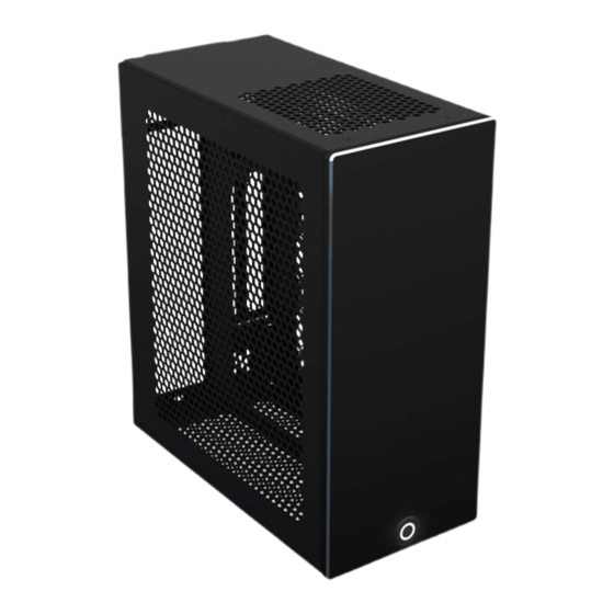
VELKA 3
Rev 3.0
USER MANUAL
5/OCT/23
SPECIFICATION ...................................................................................... 2
HARDWARE COMPATIBILITY ............................................................. 3
PACKAGE CONTENTS ........................................................................... 4
REQUIRED TOOLS .................................................................................. 4
CASE DISASSEMBLY ............................................................................. 5
PSU ............................................................................................................ 6
MOTHERBOARD ..................................................................................... 7
PCIE RISER CABLE ................................................................................. 8
GRAPHICS CARD .................................................................................... 9
MOTHERBOARD TRAY INSERTION ................................................. 10
SATA DRIVE .......................................................................................... 11
CLOSING THE CASE, RUBBER FOOT INSTALLATION .................. 12
TROUBLESHOOTING ........................................................................... 13
SUPPORT AND SERVICE ..................................................................... 13
Advertisement
Table of Contents

Related Manuals for Velkase VELKA 3


Summary of Contents for Velkase VELKA 3
-
Page 1: Table Of Contents
VELKASE VELKA 3 Rev 3.0 USER MANUAL 5/OCT/23 SPECIFICATION ..................2 HARDWARE COMPATIBILITY ............. 3 PACKAGE CONTENTS ................4 REQUIRED TOOLS .................. 4 CASE DISASSEMBLY ................5 PSU ......................6 MOTHERBOARD ..................7 PCIE RISER CABLE ................. 8 GRAPHICS CARD ..................9 MOTHERBOARD TRAY INSERTION .......... -
Page 2: Specification
SPECIFICATION Dimensions 184 x 99 x 219 mm (L x W x H) 7.2 x 3.9 x 8.6 in Weight 1.4 kg 3.1 lb Volume 3.99 L external; 3.81 L internal Materials Main body: 1.2 mm galvanized steel, powdercoated, stainless threaded inserts Front panel: 2.0 mm galvanized steel, powdercoated, stainless threaded... -
Page 3: Hardware Compatibility
25-30 cm end-to-end / 20-25 cm along flexible portion Connectors: 0° or 180° male to 0° or 180° female Recommended models: Velkase VC-S300G3 ; VC-S290G4 Graphics card Maximum clearance, including space for cables. Cables / PCI card require 16 mm+ if not recessed and routed within the (L x W x H) bounding box area of the board. -
Page 4: Package Contents
PACKAGE CONTENTS • Velka 3 chassis with pre-installed power button. PCIe riser cable and handle not included • 14x 3M Bumpon adhesive rubber bumpers • Hardware box; contents listed below. Quantities may vary. M3x0.5 5 mm countersunk screw M3x0.5 4 mm round... -
Page 5: Case Disassembly
CASE DISASSEMBLY • Perform initial system assembly with all components and cables outside of the case • Work on a soft, clean surface • Once complete, disassemble the case to the following state M3x0.5 10 mm round head screw x1 Not included in hardware box. -
Page 6: Psu
6-32 6 mm round head screw... -
Page 7: Motherboard
MOTHERBOARD • The CPU, CPU cooler, RAM, and storage should be installed onto the motherboard prior to this step M3x0.5 4 mm round head screw... -
Page 8: Pcie Riser Cable
PCIE RISER CABLE As viewed from the front... -
Page 9: Graphics Card
GRAPHICS CARD M3x0.5 4 mm round head screw... -
Page 10: Motherboard Tray Insertion
MOTHERBOARD TRAY INSERTION • Install the motherboard IO shield in the appropriate orientation • Pay attention to the PCIe cable to prevent it from being caught on any edges • Connect the graphics card’s power cable mid-way through insertion, and the remaining components’ power cables afterwards M3x0.5 5 mm M3x0.5 10 mm round countersunk screw... -
Page 11: Sata Drive
SATA DRIVE • Connect the SATA data and power cables to the storage drive and motherboard at this step M3x0.5 5 mm countersunk screw... -
Page 12: Closing The Case, Rubber Foot Installation
CLOSING THE CASE, RUBBER FOOT INSTALLATION • Wipe the case surface to improve rubber foot adhesion • Stick 4 adhesive rubber bumpers onto the bottom of the case according to the chosen orientation • For quieter operation and increased internal clearances, mount the side panels using the adjacent mounting holes. -
Page 13: Troubleshooting
PCIe riser cable (ex: gen 3). If there is no display output in UEFI BIOS, use onboard graphics (if available) or plug the graphics card directly into the PCIe slot without the cable to change this setting SUPPORT AND SERVICE For all inquiries, please email contact@velkase.com All user manuals: www.velkase.com/downloads...
Need help?
Do you have a question about the VELKA 3 and is the answer not in the manual?
Questions and answers