Table of Contents
Advertisement
Quick Links
1
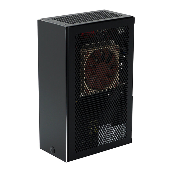
VELKA 5
Rev 2.0
USER MANUAL
Specification................................................................................................................................................. 2
Hardware compatibility ............................................................................................................................. 3
Summary of assembly steps ....................................................................................................................... 4
Disassembly ................................................................................................................................................. 5
Motherboard, CPU, cooler, memory, riser installation .......................................................................... 6
Graphics card installation ........................................................................................................................ 10
Display cable extensions .......................................................................................................................... 12
Installation into the main body ............................................................................................................... 14
2.5" drive (dedicated mount) .................................................................................................................. 16
Additional 2.5" drives .............................................................................................................................. 17
Power supply ............................................................................................................................................. 18
Front struts ................................................................................................................................................ 20
Power button ............................................................................................................................................. 21
Side panels ................................................................................................................................................. 22
Front panel ................................................................................................................................................ 24
2/NOV/2020
Advertisement
Table of Contents

Subscribe to Our Youtube Channel
Related Manuals for Velkase VELKA 5


Summary of Contents for Velkase VELKA 5
-
Page 1: Table Of Contents
VELKA 5 Rev 2.0 USER MANUAL Specification..............................2 Hardware compatibility ..........................3 Summary of assembly steps ........................4 Disassembly ..............................5 Motherboard, CPU, cooler, memory, riser installation ................6 Graphics card installation ........................10 Display cable extensions .......................... 12 Installation into the main body ....................... 14 2.5”... -
Page 2: Specification
SPECIFICATION Dimensions 177 x 99 x 285 mm (L x W x H) Weight 2.0 kg With included power supply: 3.0 kg Volume (liters) 4.9 L external, 4.6 L internal Materials and finish 5 mm anodized and sandblasted aluminum front panel 1.2 mm powder-coated galvanized steel and stainless steel body 1.0 mm powder-coated galvanized steel side panels... -
Page 3: Hardware Compatibility
HARDWARE COMPATIBILITY Motherboard Mini ITX 170 x 170 mm Power supply ENP-7660B (optional) Replaceable with Flex ATX (150 mm) CPU cooler 37 mm Graphics card Maximum clearance, including cables. Cables (L x W x H) require 16 mm if not recessed into the board. 270 x 43 x 140* mm *If card is 243 mm in length or under, max card height is 140 mm and max card + cable height is... -
Page 4: Summary Of Assembly Steps
SUMMARY OF ASSEMBLY STEPS Before starting assembly in the case, test all other components for functionality. If using a PCIe gen 4 graphics card and motherboard with the included PCIe gen 3 riser, the compatibility mode must be set to gen 3 in BIOS. Doing so will require performing the first boot with integrated graphics (if available) or with the graphics card plugged directly into the motherboard without a riser. -
Page 5: Disassembly
DISASSEMBLY If the power supply is pre-installed in your unit and you do not plan on using a 2.5” drive on the dedicated mount, you may leave it inside. 2/NOV/2020... -
Page 6: Motherboard, Cpu, Cooler, Memory, Riser Installation
MOTHERBOARD, CPU, COOLER, MEMORY, RISER INSTALLATION Remove the screws shown to allow the graphics card bracket to rotate. 2/NOV/2020... - Page 7 Install the CPU, cooler, memory, and M.2 drive onto the motherboard. Attach the motherboard to the tray and plug in the included PCIe riser. 4x round head 5 mm M3 screws 2/NOV/2020...
- Page 8 Bend the riser underneath the graphics card bracket and screw it into the standoffs. Avoid making repeat bends as this will stress the wires inside. 2x round head 5 mm M3 screws 2/NOV/2020...
- Page 9 2/NOV/2020...
-
Page 10: Graphics Card Installation
GRAPHICS CARD INSTALLATION Rotate the clip on the right, remove the bracket on the left, plug in the graphics card and reinstall the bracket on the left to keep the card in place. 2/NOV/2020... - Page 11 Ensure that the edge of the graphics card’s IO shield is flush with or below the edge of the bracket it is attached to. The graphics card should not have any protrusions past this edge. Rotate the clip back around and secure the card with two screws. 2x round head 5 mm M3 screws 2/NOV/2020...
-
Page 12: Display Cable Extensions
DISPLAY CABLE EXTENSIONS Plug the cables into the graphics card and gently fold them in such a way that they do not protrude past the riser. The cables must take up as little space as possible in order to slide easily into the frame later, but avoid making creases near the connector. - Page 13 2/NOV/2020...
-
Page 14: Installation Into The Main Body
INSTALLATION INTO THE MAIN BODY Insert the motherboard tray subassembly into the main body of the case. Attach it and then the display cable panel mounts. 2x round head 5 mm M3 screws 3x countersunk 5 mm M3 screws 6x round head 5 mm M4 screws 2/NOV/2020... - Page 15 Connect the PSU holder to the motherboard tray. 1x round head 5 mm M3 screw 2/NOV/2020...
-
Page 16: Drive (Dedicated Mount)
2.5” DRIVE (DEDICATED MOUNT) Before the power supply is installed, screw the 2.5” drive to the middle on the graphics card side. 4x countersunk 5 mm M3 screws 2/NOV/2020... -
Page 17: Additional 2.5" Drives
ADDITIONAL 2.5” DRIVES 2x round head 5 mm M3 screws Per drive: 4x countersunk 5 mm M3 screws 2/NOV/2020... -
Page 18: Power Supply
POWER SUPPLY Orient the power supply such that its vents face outwards and secure it to the rear panel. 4x 6-32 screws 2/NOV/2020... - Page 19 2/NOV/2020...
-
Page 20: Front Struts
FRONT STRUTS All cables: CPU, main motherboard, graphics card, 2.5” drive, must be plugged in before this step. Complete the main body of the case by installing the two struts in the front. 4x countersunk 5 mm M3 screws 2/NOV/2020... -
Page 21: Power Button
POWER BUTTON Remove the bottom bracket temporarily to install the power button. Use the hex nut to fix the button in place, then reinstall the bottom bracket. Consult your motherboard manual for the front panel header pin layout and plug in the power button before proceeding to the next step. Button is enlarged for clarity. -
Page 22: Side Panels
SIDE PANELS Power button cables must be plugged into the motherboard prior to this step. The side panels have three positions. Spacing them farther away from the body of the case will result in quieter operation. 0 mm spacing 2 mm spacing (experimental) 4 mm spacing (experimental) If using the experimental 2 or 4 mm spacing, adhesive rubber feet may be... - Page 23 6x round head or countersunk 5 mm M3 screws 2/NOV/2020...
-
Page 24: Front Panel
FRONT PANEL Slide in the front panel while carefully inserting the power button’s cable into the case. Secure the front panel to the rest of the case at the top and bottom. For an easier fit, re-position the brackets on the inside of the front panel away from the edges.
Need help?
Do you have a question about the VELKA 5 and is the answer not in the manual?
Questions and answers