Table of Contents
Advertisement
Quick Links
1
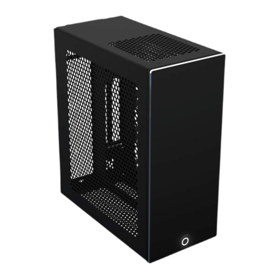
VELKA 3
Rev 2.0
USER MANUAL
Specification................................................................................................................................................. 2
Hardware compatibility ............................................................................................................................. 3
Summary of assembly steps ....................................................................................................................... 4
Disassembly ................................................................................................................................................. 5
CPU, memory, M.2 drive, and motherboard installation ...................................................................... 6
Graphics card .............................................................................................................................................. 7
Installation into the main body ................................................................................................................. 8
Power supply ............................................................................................................................................. 10
2.5" drive (dedicated mount) .................................................................................................................. 11
Front struts ................................................................................................................................................ 12
Power button ............................................................................................................................................. 14
Side panels ................................................................................................................................................. 15
Front panel ................................................................................................................................................ 17
2/NOV/2020
Advertisement
Table of Contents

Subscribe to Our Youtube Channel
Related Manuals for Velkase VELKA 3


Summary of Contents for Velkase VELKA 3
-
Page 1: Table Of Contents
VELKA 3 Rev 2.0 USER MANUAL Specification..............................2 Hardware compatibility ..........................3 Summary of assembly steps ........................4 Disassembly ..............................5 CPU, memory, M.2 drive, and motherboard installation ..............6 Graphics card .............................. 7 Installation into the main body ......................... 8 Power supply ............................. -
Page 2: Specification
SPECIFICATION Dimensions 189 x 96 x 218 mm (L x W x H) Weight 1.5 kg With included power supply: 2.6 kg Volume (liters) 3.9 L external, 3.7 L internal Materials and finish 5 mm anodized and sandblasted aluminum front panel 1.2 mm powder-coated galvanized steel and stainless steel body 1.0 mm powder-coated galvanized steel side panels... -
Page 3: Hardware Compatibility
HARDWARE COMPATIBILITY Motherboard Mini ITX 170 x 170 mm Power supply ENP-7660B (optional) Replaceable with Flex ATX (150 mm) CPU cooler 37 mm Graphics card Maximum clearance, including cables. Cables (L x W x H) require 16 mm if not recessed into the board. 175 x 43 x 148 mm 178 x 40 x 148 mm Memory... -
Page 4: Summary Of Assembly Steps
SUMMARY OF ASSEMBLY STEPS Before starting assembly in the case, test all other components for functionality. If using a PCIe gen 4 graphics card and motherboard with the included PCIe gen 3 riser, the compatibility mode must be set to gen 3 in BIOS. Doing so will require performing the first boot with integrated graphics (if available) or with the graphics card plugged directly into the motherboard without a riser. -
Page 5: Disassembly
DISASSEMBLY It is recommended to work with the case on a soft surface such as the included foam until rubber feet are installed. 2/NOV/2020... -
Page 6: Cpu, Memory, M.2 Drive, And Motherboard Installation
CPU, MEMORY, M.2 DRIVE, AND MOTHERBOARD INSTALLATION Install the CPU, cooler, memory, and M.2 drive onto the motherboard. Attach the motherboard to the tray and plug in the included PCIe riser. 4x round head 5 mm M3 screws 2/NOV/2020... -
Page 7: Graphics Card
GRAPHICS CARD Screw in the PCIe riser on the opposite side and connect the graphics card. 2x round head 5 mm M3 screws Graphics card IO shield must be on the outside of the part highlighted in as shown 2/NOV/2020... -
Page 8: Installation Into The Main Body
INSTALLATION INTO THE MAIN BODY Insert the subassembly from the previous step into the frame. 2x countersunk 5 mm M3 screws 2x round head 5 mm M3 screws 2/NOV/2020... - Page 9 Screw in middle subassembly with all components at the bottom and on the left side. Only screw in the right screw after installing the power supply. 3x countersunk 5 mm M3 screws 2/NOV/2020...
-
Page 10: Power Supply
POWER SUPPLY Slide in the power supply in the orientation shown and only attach it to the main body with the middle screw. Screw in the last PSU holder screw only after installation, otherwise, the PSU may not slide in easily. 1x countersunk 5 mm M3 screw 1x round head 6... -
Page 11: Drive (Dedicated Mount)
2.5” DRIVE (DEDICATED MOUNT) Slide in the 2.5” drive from the front and secure it to the main body of the case. Connect all cables after this step. 3x countersunk 5 mm M3 screws 2/NOV/2020... -
Page 12: Front Struts
FRONT STRUTS All cables must be plugged in before this step. Complete the main body by installing the two struts in the front. 4x countersunk 5 mm M3 screws 2/NOV/2020... - Page 13 2/NOV/2020...
-
Page 14: Power Button
POWER BUTTON Remove the bottom bracket temporarily to install the power button. Use the hex nut to fix the button in place, then reinstall the bottom bracket. Consult your motherboard manual for the front panel header pin layout and plug in the power button before proceeding to the next step. Button is enlarged for clarity. -
Page 15: Side Panels
SIDE PANELS Power button cables must be plugged into the motherboard prior to this step. The side panels have three positions. Spacing them farther away from the body of the case will result in quieter operation. 0 mm spacing 2 mm spacing (experimental) 4 mm spacing (experimental) If using the experimental 2 or 4 mm spacing, adhesive rubber feet may be... - Page 16 3x 6-32 screws 2x round head or countersunk 5 mm M3 screws 2/NOV/2020...
-
Page 17: Front Panel
FRONT PANEL Slide in the front panel while carefully inserting the power button’s cable into the case. Secure the front panel to the frame at the bottom and the top. For an easier fit, re-position the brackets on the inside of the front panel away from the edges.
Need help?
Do you have a question about the VELKA 3 and is the answer not in the manual?
Questions and answers