Table of Contents
Advertisement
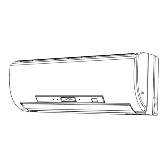
SPLIT-TYPE AIR CONDITIONERS
INDOOR UNIT
SERVICE MANUAL
Models
MSZ-FE09NA
MSZ-FE12NA
MSZ-FE18NA
MSZ-FE09NA
MSZ-FE12NA
NOTE:
RoHS compliant products have <G> mark on the spec name plate.
Revision B:
• MSZ-FE09NA -
been added.
Please void OBH542 REVISED EDITION-A.
MSZ-FE09NA
MSZ-FE12NA
CONTENTS
2. PART NAMES AND FUNCTIONS ····················· 3
3. SPECIFICATION ················································ 5
4. OUTLINES AND DIMENSIONS ························ 6
5. WIRING DIAGRAM ············································ 7
6. REFRIGERANT SYSTEM DIAGRAM ··············· 9
7. SERVICE FUNCTIONS ··································· 10
8. MICROPROCESSOR CONTROL ··················· 12
9. TROUBLESHOOTING ····································· 22
10. DISASSEMBLY INSTRUCTIONS ···················· 36
PARTS CATALOG (OBB542)
and MSZ-FE12NA -
8
No. OBH542
REVISED EDITION-B
-
8
-
8
Outdoor unit service manual
MUZ-FE•NA Series (OBH543)
MXZ-A·NA Series
(OB444)
MXZ-B·NA Series
(OB560)
·······································
have
8
2
Advertisement
Table of Contents

Subscribe to Our Youtube Channel
Related Manuals for Mitsubishi Electric Mr.Slim MUZ-FE NA Series


Summary of Contents for Mitsubishi Electric Mr.Slim MUZ-FE NA Series
-
Page 1: Table Of Contents
Revision B: • MSZ-FE09NA - and MSZ-FE12NA - have been added. Please void OBH542 REVISED EDITION-A. SPLIT-TYPE AIR CONDITIONERS INDOOR UNIT No. OBH542 SERVICE MANUAL REVISED EDITION-B Models MSZ-FE09NA MSZ-FE09NA MSZ-FE12NA MSZ-FE12NA MSZ-FE18NA Outdoor unit service manual MUZ-FE•NA Series (OBH543) MXZ-A·NA Series (OB444) MXZ-B·NA Series... -
Page 2: Technical Changes
Use the specifi ed refrigerant only Never use any refrigerant other than that specified. Doing so may cause a burst, an explosion, or fire when the unit is being used, serviced, or disposed of. Correct refrigerant is specified in the manuals and on the spec labels provided with our products. We will not be held responsible for mechanical failure, system malfunction, unit breakdown or accidents caused by failure to follow the instructions. -
Page 3: Part Names And Functions
PART NAMES AND FUNCTIONS MSZ-FE09NA MSZ-FE12NA Display section AREA lamp POWER lamp Operation indicator Remote control lamp receiving section Front panel Air filter Air inlet Remote controller Platinum deodorizing filter Anti-allergy Enzyme Filter i-see Sensor Air outlet Emergency operation switch (E.O. SW) Horizontal vane Heat exchanger AREA lamp indicates AREA setting... - Page 4 MSZ-FE18NA Front panel Air filter (Nano platinum filter) Air cleaning filter (Electrostatic anti-alergy enzyme filter) Air inlet Air outlet Remote controller Heat exchanger Horizontal vane Display section ACCESSORIES Models MSZ-FE09/12NA MSZ-FE18NA Installation plate Installation plate fi xing screw 4 × 25 mm Remote controller holder Fixing screw for 3.5 ×...
-
Page 5: Specification
SPECIFICATION Indoor model MSZ-FE09NA MSZ-FE12NA MSZ-FE18NA Power supply V, phase, Hz 208/230 , 1 , 60 Max. fuse size (time delay)/ Disconnect switch Min. circuit ampacity Fan motor F.L.A 0.76 COOL Dry 381 - 339 - 226 - 162 410 - 381 - 226 - 162 738 - 628 - 469 - 388 Airfl... -
Page 6: Outlines And Dimensions
OUTLINES AND DIMENSIONS Unit: inch MSZ-FE09NA MSZ-FE12NA 7/16 X 1 Oblong hole 7/16 X 13/16 Oblong hole 8-7/8 8-7/8 2-1/2 2-1/2 Installation plate 31-3/8 30-7/8 6-1/8 6-1/8 2-1/8 13-9/16 2-11/16 Indoor unit Wall hole ø2-9/16 Air in Installation plate 10-1/8 Piping 27-1/16 2-3/16... -
Page 7: Wiring Diagram
WIRING DIAGRAM MSZ-FE09NA MSZ-FE12NA... - Page 8 MSZ-FE09NA MSZ-FE12NA MSZ-FE18NA...
-
Page 9: Refrigerant System Diagram
REFRIGERANT SYSTEM DIAGRAM MSZ-FE09NA MSZ-FE12NA Refrigerant pipe Unit: inch (with heat insulator) Indoor coil Indoor thermistor heat RT12 (main) exchanger Flared connection Indoor coil thermistor RT13 (sub) Room temperature thermistor RT11 Flared connection Refrigerant flow in cooling Refrigerant pipe Refrigerant flow in heating (with heat insulator) MSZ-FE18NA Refrigerant pipe ø5/8... -
Page 10: Service Functions
SERVICE FUNCTIONS MSZ-FE09NA MSZ-FE12NA MSZ-FE18NA 7-1. TIMER SHORT MODE For service, set time can be shortened by short circuit of JPG and JPS the indoor electronic control P.C. board. The time will be shortened as follows. (Refer to 9-7.) Set time: 1-minute 1-second Set time: 3-minute 3-second (It takes 3 minutes for the compressor to start operation. - Page 11 7-3. AUTO RESTART FUNCTION When the indoor unit is controlled with the remote controller, the operation mode, the set temperature, and the fan speed are memorized by the indoor electronic control P.C. board. “AUTO RESTART FUNCTION” automatically starts operation in the same mode just before the shutoff of the main power.
-
Page 12: Microprocessor Control
MICROPROCESSOR CONTROL MSZ-FE09NA MSZ-FE12NA MSZ-FE18NA WIRELESS REMOTE CONTROLLER MSZ-FE09NA MSZ-FE12NA Signal transmitting section Operation display section VANE CONTROL button OPERATE/STOP FAN SPEED CONTROL button (ON/OFF) button OFF TIMER button OPERATION SELECT button ON TIMER button POWERFUL button TIME SET buttons Temperature buttons FORWARD button BACKWARD button... - Page 13 INDOOR UNIT DISPLAY SECTION Operation indicator lamp MSZ-FE09NA MSZ-FE12NA The lamps at the center of the indoor unit indicates the operation state. Lamp Operation state AREA Refer to 8-7. Lamp lights during operation. POWER Lamp blinks in abnormal condition. MSZ-FE18NA The operation indicator at the right side of the indoor unit indicates the operation state.
- Page 14 8-3. HEAT ( ) OPERATION (1) Press OPERATE/STOP (ON/OFF) button. POWER lamp (MSZ-FE09/12NA)/OPERATION INDICATOR lamp (MSZ-FE18NA) of the indoor unit turns on with a beep tone. (2) Select HEAT mode with OPERATION SELECT button. (3) Press TEMPERATURE buttons (TOO WARM or TOO COOL button) to select the desired temperature. The setting range is 61 ~ 88°F (16 ~ 31°C).
- Page 15 8-5. AUTO VANE OPERATION 1. Horizontal vane (1) Vane motor drive These models are equipped with a stepping motor for the horizontal vane. The rotating direction, speed, and angle of the motor are controlled by pulse signals (approx. 12 V) transmitted from indoor microprocessor. (2) The horizontal vane angle and mode change as follows by pressing VANE CONTROL button.
- Page 16 (8) Cold air prevention in HEAT operation The horizontal vane position is set to Upward. NOTE: When 2 or more indoor units are operated with multi outdoor unit, even if any indoor unit turns thermostat off, this control does not work in the indoor unit. (9) ECONO COOL ( ) operation (ECONOmical operation) (MSZ-FE18NA) When ECONO COOL button is pressed in COOL mode, set temperature is automatically set 2°C higher.
- Page 17 8-6. i-see CONTROL OPERATION (MSZ-FE09NA MSZ-FE12NA) The sensors constantly measure the room and floor/wall temperatures to automatically adjust to the set temperature by esti- mating the temperature actually perceived by a person inside the room (“sensory temperature”). Advantages · The air inside the room is conditioned quickly to a comfortable condition. ·...
- Page 18 Indoor unit installation location and air-conditioning area Installed at left Installed at center Installed at right LEFT RIGHT LEFT RIGHT LEFT RIGHT ·Be sure to set the slide switch inside the remote controller to an appropriate position according to the installed position of the indoor unit.
- Page 19 Operation and operating range i-see sensor moves 30 degrees from the center in both right and left side. i-see Sensor turning to the center i-see Sensor turning to the right i-see Sensor turning to the left i-see Sensor operates as follows in accordance with AREA setting made with the remote controller. “AUTO”...
- Page 20 PROGRAM TIMER • OFF timer and ON timer can be used in combination. The timer of the set time that is reached first will operate first. • “ ” and “ ” display shows the order of OFF timer and ON timer operation. (Example 1) The current time is 8:00 PM.
- Page 21 8-10. 3-MINUTE TIME DELAY OPERATION When the system turns OFF, compressor will not restart for 3 minutes as 3-minute time delay function operates to protect compressor from overload. 8-11. Changing temperature indication (°F/°C) • The preset unit is °F. • °F →...
-
Page 22: Troubleshooting
TROUBLESHOOTING MSZ-FE09NA MSZ-FE12NA MSZ-FE18NA 9-1. CAUTIONS ON TROUBLESHOOTING 1. Before troubleshooting, check the following 1) Check the power supply voltage. 2) Check the indoor/outdoor connecting wire for miswiring. 2. Take care of the following during servicing 1) Before servicing the air conditioner, be sure to turn off the unit first with the remote controller, and then after confirming the horizontal vane is closed, turn off the breaker and/or disconnect the power plug. - Page 23 9-2. FAILURE MODE RECALL FUNCTION Outline of the function This air conditioner can memorize the abnormal condition which has occurred once. Even though LED indication listed on the troubleshooting check table (9-4.) disappears, the memorized failure details can be recalled. This mode is very useful when the unit needs to be repaired for the abnormality which does not recur.
- Page 24 2. Indoor unit failure mode table POWER lamp Abnormal point Condition Remedy Upper lamp (Failure mode) Not lighted Normal — — The room temperature thermistor short or open 1-time fl ash every Room temperature Refer to the characteristics of the room temperature circuit is detected every 8 seconds during op- 0.5-second thermistor...
- Page 25 9-3. INSTRUCTION OF TROUBLESHOOTING Start Indoor unit operates. Indoor unit oper- Indoor unit does OPERATION INDICATOR Outdoor unit does not receive the ates. lamp on the indoor unit is not operate normally. Outdoor unit signal from re- fl ashing on and off. mote controller.
- Page 26 9-4. TROUBLESHOOTING CHECK TABLE Before taking measures, make sure that the symptom reappears for accurate troubleshooting. When the indoor unit has started operation and the following detection method has detected an abnormality (the first detection after the power ON), the indoor electronic control P.C. board turns OFF the indoor fan motor with OPERATION INDICATOR lamp flashing.
- Page 27 OPERATION INDICATOR L AREA R POWER Abnormal Operation indicator lamp Symptom Condition Remedy point POWER lamp is lighted. MXZ type The operation mode of the each indoor unit AREA lamps fl ash. Outdoor unit Operation is differently set to COOL (includes DRY) and •...
- Page 28 9-6. TROUBLESHOOTING FLOW A Check of indoor fan motor The indoor fan motor error has occurred, and the indoor fan does not operate. Turn OFF the power supply. Pay enough attention to the high voltage on the fan motor connector CN211. Turn ON the power supply, wait 5 seconds or more, and then press EMERGENCY OPERATION switch.
- Page 29 B Check of remote controller and indoor electronic control P.C. board Check if the remote controller is exclusive for this air conditioner. MSZ-FE09NA MSZ-FE12NA Press OPERATE/STOP (ON/OFF) button on the remote controller. Is LCD display on the remote controller Replace the batteries. (Refer to 9-1.4.) visible? (Not clear) Remove the batteries, then set them back...
- Page 30 C Check of indoor electronic control P.C. board and indoor fan motor MSZ-FE09NA MSZ-FE12NA Turn OFF the power supply. Remove indoor fan motor connector CN211, vane motor connector CN151 and the i-see Measure the resistance of the i-see Short circuit: Sensor motor connector CN110 from the Sensor motor coil.
- Page 31 MSZ-FE18NA Turn OFF the power supply. Remove indoor fan motor connector CN211 and Short circuit: Measure the resistance between CN211 Replace the indoor fan motor. vane motor connector CN151 from the indoor electronic of the indoor fan motor connector. control P.C. board and turn ON the power supply. Does the unit operate with the remote controller? Short circuit: Measure the resistance of the horizontal vane...
- Page 32 D How to check miswiring and serial signal error Turn OFF the power supply. Is there rated voltage in the power supply? Check the power supply. Turn ON the power supply. Check the wiring. Is there rated voltage between outdoor terminal block S1 and S2? Press EMERGENCY OPERATION switch once.
- Page 33 E Electromagnetic noise enters into TV sets or radios Is the unit grounded? Ground the unit. Is the distance between the antennas Extend the distance between the antennas and and the indoor unit within 9.91 ft., or is the indoor unit, and/or the antennas and the the distance between the antennas and outdoor unit.
- Page 34 9-7. TEST POINT DIAGRAM AND VOLTAGE MSZ-FE09NA MSZ-FE12NA 1. Indoor electronic control P.C. board Cement resistor 5 VDC 12 VDC (R111) Indoor fan motor (CN211) 294/325 VDC (-) Fiducial terminal of cathode side on measur- ing high-voltage DC 15 VDC (+)3 - 6 VDC (+)0 or 15 VDC Power supply input...
- Page 35 MSZ-FE18NA 4. Indoor terminal P.C. board, Indoor electronic control P.C. board, Power monitor receiver SW P.C. board Indoor terminal P.C. board Indoor electronic control P.C. board Release of Auto restart function Indoor coil thermistor Solder the Jumper wire to JR07. Terminal Varistor Fuse...
-
Page 36: Disassembly Instructions
DISASSEMBLY INSTRUCTIONS <"Terminal with locking mechanism" Detaching points> The terminal which has the locking mechanism can be detached as shown below. There are two types (refer to (1) and (2)) of the terminal with locking mechanism. The terminal without locking mechanism can be detached by pulling it out. Check the shape of the terminal before detaching. - Page 37 OPERATING PROCEDURE PHOTOS 2. Removing the electronic control P.C. board, the Photo 2 power monitor receiver P.C. board, i-see Sensor, SW P.C. board and the terminal block Screw of the (1) Remove the panel (Refer to 1.) and the corner box. conduit cover (2) Remove the screw of the conduit cover.
- Page 38 OPERATING PROCEDURE PHOTOS Photo 5 3. Removing the electrical box (1) Remove the panel (Refer to 1.) and the corner box. (2) Remove the indoor/outdoor connecting wire, the sensor holder, the electrical cover and the ground wire. (Refer to 2.) (3) Disconnect the following connectors on the electronic con- trol P.C.
- Page 39 OPERATING PROCEDURE PHOTOS 6. Removing the horizontal vane motor Photo 8 Screws of the horizontal (1) Remove the nozzle assembly. (Refer to 4.) vane motor unit cover (2) Remove the screws of the horizontal vane motor unit, and pull out the horizontal vane motor unit. (3) Remove the screws of the horizontal vane motor unit cover.
- Page 40 10-2. MSZ-FE18NA NOTE: Turn OFF power supply before disassembly. OPERATING PROCEDURE PHOTOS 1. Removing the panel Photo 1 (1) Remove the horizontal vanes. Front panel Horizontal vanes (2) Remove the screw caps of the panel. Remove the screws of the panel. (3) Hold the lower part of both ends of the panel and pull it slightly toward you, and then remove the panel by pushing it upward.
- Page 41 OPERATING PROCEDURE PHOTOS 3. Removing the indoor electrical box Photo 3 (1) Remove the panel (Refer to 1.) and the corner box. Upper catch (2) Remove the indoor/outdoor connecting wire. (Refer to 2 (2)-(4).) (3) Remove the ground wire connected to the indoor heat Indoor electri- exchanger from the electrical box.
- Page 42 OPERATING PROCEDURE PHOTOS Photo 5 5. Removing the vertical vane motor unit (1) Remove the nozzle assembly. (Refer to 4.) (2) Remove the crank of the vertical vane motor unit from the arm of the vertical vane. (3) Remove the screw of the vertical vane motor unit, and pull the vertical vane motor unit.
- Page 43 OPERATING PROCEDURE PHOTOS 7. Removing the water cut, the indoor fan motor, Photo 8 the indoor coil thermistor, and the line flow fan (1) Remove the panel (Refer to 1.) and the corner box. (2) Remove the power monitor receiver holder, the electri- cal box and the nozzle assembly.
- Page 44 HEAD OFFICE: TOKYO BLDG., 2-7-3, MARUNOUCHI, CHIYODA-KU, TOKYO 100-8310, JAPAN © Copyright 2009 MITSUBISHI ELECTRIC CO., LTD Distributed in Apr. 2011. No. OBH542 REVISED EDITION-B Distributed in Sep. 2010. No. OBH542 REVISED EDITION-A 5 New publication, effective Apr. 2011 Distributed in Jul. 2009. No. OBH542 5 Specifications subject to change without notice.
Need help?
Do you have a question about the Mr.Slim MUZ-FE NA Series and is the answer not in the manual?
Questions and answers