Table of Contents
Advertisement
Available languages
Available languages
Quick Links
Advertisement
Chapters
Table of Contents

Subscribe to Our Youtube Channel
Related Manuals for GLOBALO Lonatio Isola 90


Summary of Contents for GLOBALO Lonatio Isola 90
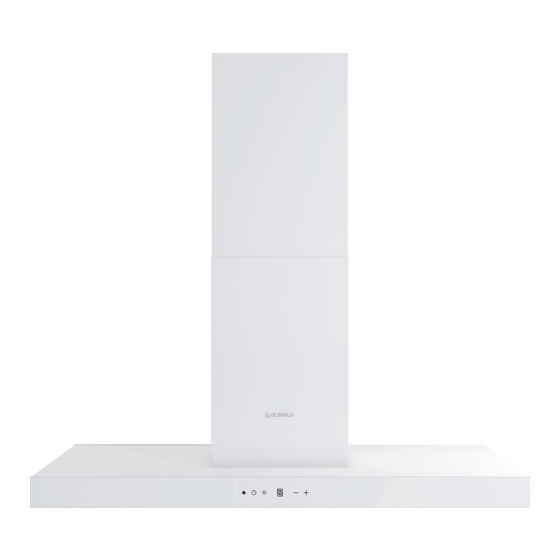
- Page 1 PL Okap kuchenny wyspowy EN Island range hood DE Inselhaube Lonatio Isola Lonatio Isola 90 PL Instrukcja montażu i użytkowania EN Operating and installation instructions DE Gebrauchs- und Montageanleitung...
-
Page 2: Table Of Contents
Spis treści OGÓLNE WARUNKI BEZPIECZEŃSTWA I MONTAŻU OCHRONA ŚRODOWISKA DANE TECHNICZNE MONTAŻ I EKSPLOATACJA TRYB PRACY Z WYCIĄGIEM LUB ZAMKNIĘTYM OBIEGIEM POWIETRZA PRZYGOTOWANIA PRZED INSTALACJĄ OKAPU 10-14 INSTALACJA OKAPU FILTR WĘGLOWY PODŁĄCZENIE ELEKTRYCZNE CZYSZCZENIE I KONSERWACJA WYMIANA PASKA LED FILTR PRZECIWTŁUSZCZOWY 16-17 STEROWANIE PRACĄ... - Page 3 Zalecamy również jej zachowanie, aby móc z niej skorzystać w każdej chwili. Zespół GLOBALO Dla zapewnienia Państwu maksymalnego bezpieczeństwa w użytkowaniu zakupionego urządze- nia, najważniejsze treści niniejszej instrukcji zostały wyróżnione następującym symbolem: SYMBOL UWAGA, WSKAZUJE NA MOŻLIWE NIEBEZPIECZEŃSTWA W UŻYTKOWANIU OKAPU.
-
Page 4: Ogólne Warunki Bezpieczeństwa I Montażu
OGÓLNE WARUNKI BEZPIECZEŃSTWA I MONTAŻU • Zachowaj niniejszą instrukcję obsługi, aby móc z niej skorzystać w każdej chwili. • Zapoznaj się z treścią niniejszej instrukcji obsługi, która zawiera dokładne informacje dotyczące instalacji, montażu i konserwacji okapu. • Okap może różnić się pod względem wyglądu od okapu przedstawionego na rysunkach w niniejszej instrukcji, ale zalecenia dotyczące obsługi, konserwacji i montażu pozostają... -
Page 5: Ochrona Środowiska
OCHRONA ŚRODOWISKA Urządzenie zostało wykonane z wysokiej jakości materiałów, które nadają się do ponownego wykorzystania. Symbol przekreślonego kontenera na odpady umieszczony na wyrobie (Rys. 1) oznacza, że podlega on selektywnej zbiórce, zgodnie z postanowieniami Dyrektywy Parlamentu Europejskiego i Rady 2012/19/UE. Jeżeli na wyrobie umieszczony jest symbol przekreślonego kontenera na odpady (Rys. -
Page 6: Dane Techniczne
DANE TECHNICZNE Dane techniczne zawarte w niniejszej instrukcji obsługi oraz na dołączonych do okapu etykietach zostały uzyskane poprzez wykonanie pomiarów i obliczeń zgodnie z wymogami rozporządzenia UE nr 65/2014 oraz 66/2014. LONATIO ISOLA 90 Napięcie: 220 – 240V Częstotliwość: ~50 Hz... - Page 7 UWAGA! ŚRUBY I ELEMENTY MOCUJĄCE STOSUJ ZGODNIE Z INSTRUKCJĄ. W PRZECIWNYM WYPADKU MOŻE ZAISTNIEĆ RYZYKO PORAŻENIA PRĄDEM ELEKTRYCZNYM. Minimalna odległość zawieszenia okapu pomiędzy powierzchnią urządzenia grzewczego (ku- chenka gazowa, elektryczna), a najniższą częścią okapu kuchennego (ilustracja poniżej) powinna wynosić, nie mniej niż 55 cm dla kuchenek o zasilaniu elektrycznym i nie mniej niż 65 cm dla kuchenek gazowych.
-
Page 8: Tryb Pracy Z Wyciągiem Lub Zamkniętym Obiegiem Powietrza
TRYB PRACY Z WYCIĄGIEM LUB Z ZAMKNIĘTYM OBIEGIEM POWIETRZA Przy trybie z wyciągiem powietrza (Rys. 4) opary zostają wyprowadzone do atmosfery kanałem wentylacyjnym przez system wyciągu. Rys. 4 Przy trybie z obiegiem zamkniętym powietrza opary zostają uwolnione od drobinek tłuszczu oraz zapachów i ponownie wydmuchiwane do kuchni (Rys. -
Page 9: Przygotowania Przed Instalacją Okapu
• Sprawdź, czy w miejscach w których będą wykonane wiercenia nie znajdują się przewody in- stalacyjne (elektryczne, hydrauliczne itp.). • Przygotuj następujące narzędzia: miarkę, ołówek, wiertarkę / wkrętarkę, wiertło Ø8 mm, śru- bokręt, poziomicę. UWAGA! ZACHOWAJ OSTROŻNOŚĆ, ABY NIE PORYSOWAĆ OKAPU. LONATIO ISOLA 90 Rys. 6... -
Page 10: Instalacja Okapu
INSTALACJA OKAPU 1. Rozpakuj okap, uważając żeby nie uszkodzić elementów. Rys.7 A - Okap z silnikiem D - Stelaż G - Wkręt 4,2x13 B - Maskownica górna E - Kątowniki H - Śruba M4x12 C - Maskownica dolna F - Wkręt 3,5x9,5 2. - Page 11 3. Przykręć stelaż D do sufitu za pomocą wkrętów. Dokręcić wszystkie cztery wkręty. Rys. 9 4. Do powieszonego podwieszonego stelaża D przykręć kątowniki E. Każdy kątownik przykręć w dwóch miejscach za pomocą wkrętów G. Kątowniki posiadają regulację w zakresie 800-920mm. Regulacja Rys.
- Page 12 5. Zmontować maskownicę B na stelażu. Następnie przykręć maskownicę do stelaża za pomocą wkrętów F. Rys. 11 6. Nasuń drugą część maskownicy C. Rys. 12...
- Page 13 7. Przykręć ośmioma śrubami H okap z silnikiem A do kątowników. Rys. 13...
- Page 14 8. Do powieszonego okapu z silnikiem podłączyć rurę z wyciągiem powietrza. Następnie podłączyć kabel sieciowy do prądu. Jeśli całość jest podłączona można nasunąć maskownicę C. Rys. 14 UWAGA! PO ZAKOŃCZENIU MONTAŻU NALEŻY USUNĄĆ WSZYSTKIE FOLIE ZABEZPIECZAJĄCE Z OKAPU I JEGO ELEMENTÓW (FILTRY, MASKOWNICE ITP.)
-
Page 15: Filtr Węglowy
FILTR WĘGLOWY Okap może być wyposażony w filtr węglowy. Zastosuj go wyłącznie wtedy, kiedy okap nie jest podłączony do przewodu wentylacyjnego. Umieść filtr na filtrze przeciwtłuszczowym jak poka- zuje to Rys.15 Wymiany filtra węglowego dokonuj co 3-6 miesięcy. MONTAŻ FILTRA DEMONTAŻ... -
Page 16: Czyszczenie I Konserwacja
CZYSZCZENIE I KONSERWACJA Przed wykonaniem jakichkolwiek czynności związanych z konserwacją urządzenia, wyjmij wtycz- kę z gniazdka. Do czyszczenia okapu stosuj łagodne środki myjące. Nie używaj środków ściernych. Czyszczenie okapu wykonuj przynajmniej raz w miesiącu lub co 35 godzin pracy okapu. Do mycia okapu w żadnym wypadku NIE UŻYWAJ ŚRODKÓW NA BAZIE ALKOHOLU. -
Page 17: Co Robić W Razie Napotkania Problemu
Wyświetlacz LED Wybrany stopień prędkości (1,2,3,4), będzie pokazany przy pomocy wskaźnika stopnia prędkości i numerycznego Regulacja prędkości Naciśnięcie klawisza minus „–” spowoduje zmniejszenie prędkości turbiny. Naciśnięcie klawisza plus „+” spowoduje zwiększenie prędkości turbiny. Włączanie i wyłączanie silnika okapu • naciśnięcie klawisza „+” - włącza silnik •... -
Page 18: Etykieta Energetyczna
Wydajność jest niewystarczająca / okap pracuje głośniej niż powinien: • Sprawdź, czy przekrój przewodu wentylacyjnego jest wystarczający i czy nie ma zbyt dużo załamań i ostrych kątów. • Sprawdź, czy w kanale wentylacyjnym nie zakleszczyła się klapa ciągu powrotnego (jeśli taka jest opcjonalnie zamontowana). -
Page 19: Sposoby Zmniejszenia Wpływu Procesu Gotowania Na Środowisko
Model: ___________________ Numer serii: ___________________ Te informacje można znaleźć na tabliczce znamionowej. Znajduje się ona wewnątrz okapu i jest widoczna po zdjęciu metalowych filtrów. Model LONATIO ISOLA 90 Moc silnika 250 W Moc oświetlenia 2x6 W Moc całkowita 262 W Napięcie /... -
Page 20: Rozwiązywanie Problemów
Zgłoszenie naprawy okapu można dokonać poprzez formularz dostępny na stronie www.globalo.pl/serwis/. ROZWIĄZYWANIE PROBLEMÓW Objawy Przyczyny wystąpienia Sposoby naprawy Po 35 godzinach pracy okap sygnalizuje Naciśnij i przytrzymaj przez ok. Podczas pracy okapu na wyświetlaczu konieczność wyczyszczenia lub wymiany 6s pole „-” na panelu dotykowym. Umyj pojawia się... -
Page 21: Informacje O Gwarancji
INFORMACJE O GWARANCJI W okresie 2 lat od daty sprzedaży produktu, GLOBALO pokrywa wszystkie koszty napraw uste- rek, ewidentnie spowodowanych wadami produkcyjnymi. Z gwarancji wyłączone są żarówki, bez- pieczniki i filtry oraz wszelkiego rodzaju uszkodzenia, które powstały wskutek błędnego montażu i wadliwej instalacji wentylacyjnej. - Page 22 Table of GENERAL INFORMATION ON SAFETY AND INSTALLATION contents ENVIRONMENTAL PROTECTION TECHNICAL SPECIFICATION 26-27 INSTALLATION AND OPERATION OPERATING MODE WITH EXHAUST OR CLOSED AIR CIRCULATION PREPARATION BEFORE HOOD INSTALLATION 30-34 HOOD INSTALLATION CARBON FILTER POWER SUPPLY CONNECTION CLEANING AND MAINTENANCE LIGHT STRIPE REPLACEMENT ANTI-GREASE FILTER 36-37...
- Page 23 We also recommend that you keep the manual in an easily accessible place so that you can consult it at any time. GLOBALO team In order to ensure the maximum safety of the device, the most important information has been marked with the following symbol: THE CAUTION SYMBOL INDICATES POSSIBLE DANGERS WHEN USING THE HOOD.
- Page 24 GENERAL INFORMATION ON SAFETY AND INSTALLATION • Keep the manual in an easily accessible place so that you can consult it at any time. • This manual contains detailed information on the installation and maintenance of the range hood. • The product may slightly differ from the range hood presented in this manual, but the recommendations regarding operation, maintenance and installation apply to the same extent.
-
Page 25: Environmental Protection
ENVIRONMENTAL PROTECTION The product is made of high quality recyclable materials. The symbol of a crossed-out wheelie bin on the product (Fig. 1) indicates that the end users should segregate the product from other waste at end-of-life, in accordance with the provisions of Directive 2012/19/EU of the European Parliament and of the Council. -
Page 26: Technical Specification
The technical specification presented in this manual and on the labels placed on the product is based on measurements and calculations in accordance with the requirements of EU Regulation 65/2014 and 66/2014. LONATIO ISOLA 90 Supply Voltage 220 – 240V... - Page 27 CAUTION! USE SCREWS AND FASTENERS APPROVED IN THE MANUAL TO AVOID THE RISK OF ELECTRIC SHOCK. The minimum distance between the surface of the cooker and the lowest part of the range hood (see figure below) must be at least 55 cm for electric cookers and 65 cm for gas cookers. If the cooker manual indicates a greater distance than specified above, follow the instructions in the cooker manual.
-
Page 28: Operating Mode With Exhaust Or Closed Air Circulation
OPERATING MODE WITH EXHAUST OR CLOSED AIR CIRCULATION In case of operation with air extraction (Fig. 4), the vapours are exhausted to the atmosphere through the ventilation duct by means of the extraction system. Fig. 4 With the air recirculation mode, the vapours are freed from grease particles and odours and blown back into the kitchen (Fig. -
Page 29: Preparation Before Hood Installation
• Make sure there are no lines of electric and plumbing installations in places where holes will be drilled. • Prepare the following tools: tape measure, pencil, drill/driver, Ø8 mm drill bit, screwdriver, level. CAUTION! TAKE CARE NOT TO SCRATCH THE HOOD. LONATIO ISOLA 90 Fig. 6... -
Page 30: Hood Installation
HOOD INSTALLATION 1. Unpack the hood, taking care not to damage the components. Decide whether the hood will Fig.7 A - Hood with motor D - Hanger G - Screw 4,2x13 B - Top grille E - Angles H - Bolt M4x12 C - Bottom grille F - Screw 3,5x9,5 2. - Page 31 3. Screw the rack D to the ceiling with screws. Tighten all four screws. Fig. 9 4. Screw angle brackets E to the suspended rack D. Screw each angle bracket in two places with screws G. The angles are adjustable from 800-920mm. Adjustment Fig.
- Page 32 5. Assemble the grille B on the rack. Then screw the grille to the frame using screws F. Fig. 11 6. Slide on the second part of grille C. Fig. 12...
- Page 33 7. Screw the eight bolts H of the hood with motor A to the angles. Fig. 13...
- Page 34 8. Connect the air extraction pipe to the hung hood with motor. Then connect the mains cable to the power supply. When all is connected, you can slip on the C grille. Fig. 14 CAUTION! AFTER INSTALLATION, REMOVE ALL PROTECTIVE FILMS FROM THE HOOD AND ITS COMPONENTS (FILTERS, GRILLES, ETC.)
-
Page 35: Carbon Filter
CARBON FILTER The hood can be equipped with a carbon filter. Install it only when the hood is not connected to the ventilation duct. Place the filter on the grease filter as shown in Fig.15 Replace the carbon filter every 3-6 months. FILTER ASSEMBLY FILTER DISASSEMBLY CONNECTION DIAGRAM FOR... -
Page 36: Cleaning And Maintenance
CLEANING AND MAINTENANCE Before performing any maintenance operations, unplug the device from the socket. Use mild de- tergents for cleaning. Do not use abrasive cleaning products. The hood should be cleaned at least once a month or every 35 hours of operation. DO NOT USE ALCOHOL-BASED CLEANING AGENTS. Inox parts should be cleaned with special product (e.g. -
Page 37: In Case Of Problems
LED display The selected speed level (1,2,3,4) will be indicated by the speed level indicator and the numerical Speed control Pressing the minus key “–” will reduce the turbine speed. Pressing the plus key “+” will increase the turbine speed. Switching the hood motor on and off •... -
Page 38: Energy Label
Insufficient efficiency / noisy operation: • Check whether the cross-section of the ventilation duct is sufficient and whether it has not too many bends and sharp angles. • Check if the return flap (if optionally installed) is not jammed in the ventilation duct. •... -
Page 39: Reducing The Impact Of Cooking On The Environment
7350001 GLOBALO MAX Ul. Maków 10 38-500 Sanok The identification plate shown in the figure above is only an example. The data may differ for other models. To request a hood repair, you can use the form available at www.globalo.pl/serwis/. -
Page 40: Troubleshooting
TROUBLESHOOTING Problem Possible reason Solution After 35 hours of operation, the display Press and hold down for approx. When the hood is operating, a flashing „F” indicates that the anti-grease filter needs 6s the „-” button on the panel. Clean the appears on the display*. -
Page 41: Warranty
WARRANTY Within the period of 2 years from the date of purchase of the product, GLOBALO undertakes to cover all repair costs for faults which are obviously caused by manufacturing defects. The war- ranty does not cover burnt bulbs, fuses and filters, as well as any damage due to faulty installation and ventilation system. - Page 42 Inhaltsverzeichnis 45-46 ALLGEMEINE SICHERHEITS- UND MONTAGEBEDINGUNGEN UMWELTSCHUTZ TECHNISCHE DATEN 47-48 MONTAGE UND BETRIEB ABLUFTBETRIEB ODER UMLUFTBETRIEB VORBEREITUNGEN ZUR INSTALLATION DER DUNSTABZUGSHAUBE 51-55 INSTALLATION DER DUNSTABZUGSHAUBE KOHLEFILTER ELEKTRISCHER ANSCHLUSS REINIGUNG UND WARTUNG AUSTAUSCHEN DER LED-STREIFEN FETTFILTER 57-58 STEUERUNG DER DUNSTABZUGSHAUBE WAS IST BEI PROBLEMEN ZU TUN? ENERGIEETIKETT METHODEN ZUR REDUZIERUNG DER UMWELTEINWIRKUNG DES KOCHPROZESSES KUNDENDIENST...
- Page 43 ZUGSHAUBE. FÜR IHRE SICHERHEIT SIND DIE MIT DIESEM SYMBOL GEKENNZEICHNETEN HINWEISE UNBEDINGT ZU BERÜCKSICHTIGEN! Hauptsitz der Firma GLOBALO Maków 10 Str. 38-500 Sanok Polen Tel.: +48 13 49 27 560 www.globalo.pl e-mail: biuro@globalo.pl Kundendienst: Tel.: +48 13 49 27 560 App. 3 Mobile: +48 609 055 660 e-mail: serwis@globalo.pl www.globalo.pl/serwis/...
-
Page 44: Allgemeine Sicherheits- Und Montagebedingungen
ALLGEMEINE SICHERHEITS- UND MONTAGEBEDINGUNGEN • Bewahren Sie diese Gebrauchsanleitung auf, um sie jederzeit nutzen zu können. • Lesen Sie den Inhalt dieser Gebrauchsanleitung, die detaillierte Informationen zur Installation, Montage und Wartung der Dunstabzugshaube enthält. • Die Dunstabzugshaube kann von der in Zeichnungen dieser Gebrauchsanleitung dargestellten Dunstabzugshaube abweichen, aber die Empfehlungen für Betrieb, Wartung und Montage bleiben jedoch unverändert. -
Page 45: Umweltschutz
• Kinder dürfen nicht mit dem Gerät spielen. • Reinigung und Wartung dürfen nicht von unbeaufsichtigten Kindern durchgeführt werden. ACHTUNG! DIE ZUGÄNGLICHEN TEILE KÖNNEN WÄHREND DES HERDBETRIEBS HEISS SEIN. WENN SCHRAUBEN ODER BEFESTIGUNGELEMENTE NICHT NACH VORGABEN DER GEBRAUCHS- UND MONTAGEANLEITUNG VERWENDET WERDEN, BESTEHT EINE STROMSCHLAGGEFAHR UMWELTSCHUTZ Das Gerät ist aus hochwertigen Materialien hergestellt, die wiederverwendet werden können. -
Page 46: Technische Daten
TECHNISCHE DATEN Die in dieser Gebrauchsanleitung und auf den der Dunstabzugshaube beigelegten Etiketten ge- nannten technischen Daten wurden aufgrund der nach den EU-Verordnungen Nr. 65/2014 und Nr. 66/2014 durchgeführten Messungen und Berechnungen ermittelt. LONATIO ISOLA 90 Spannung: 220 – 240V Frequenz:... - Page 47 ACHTUNG! VERWENDEN SIE SCHRAUBEN UND BEFESTIGUNGSELEMENTE GEMÄSS DER GEBRAUCHSANLEITUNG. ANDERNFALLS BESTEHT EINE STROMSCHLAGGEFAHR: Bei der aufgehängten Dunstabzugshaube darf der Mindestabstand zwischen der Herdfläche (Gasherd, Elektroherd) und der am niedrigsten gelegenen Teil der Dunstabzugshaube (siehe Bild unten) nicht weniger als 55 cm bei den mit Strom und nicht weniger als 65 cm bei den mit Gas betriebenen Herden betragen.
-
Page 48: Abluftbetrieb Oder Umluftbetrieb
ABLUFTBETRIEB ODER UMLUFTBETRIEB Beim Abluftbetrieb (Abb. 4) werden die Kochdünste über das Abluftrohr und das Abluftsystem nach draußen abgeleitet. Abb. 4 Beim Umluftbetrieb werden die Kochdünste von Fettpartikeln und Gerüchen befreit und dem Küchenraum wieder zugeführt (Abb. 5). Damit die Gerüche durch die Dunstabzugshaube absor- biert werden, ist obligatorisch ein Aktivkohlefilter zu verwenden. -
Page 49: Vorbereitungen Zur Installation Der Dunstabzugshaube
• Prüfen Sie, ob an denjenigen Stellen, wo Bohrungen durchzuführen sind, keine (elektrische, hydraulische u.dgl.) Installationsleitungen vorhanden sind. • Halten Sie folgende Werkzeuge bereit: Zollstock, Bleistift, Bohrmaschine / Handschrauber, Bohrer Ø8 mm, Schraubenzieher, Wasserwaage. ACHTUNG! MIT VORSICHT VORGEHEN: DIE DUNSTABZUGSHAUBE NICHT ANKRATZEN. LONATIO ISOLA 90 Abb. 6... -
Page 50: Installation Der Dunstabzugshaube
INSTALLATION DER DUNSTABZUGSHAUBE 1. Packen Sie den Dunstabzug aus und achten Sie dabei darauf, dass die Bauteile nicht beschädigt werden. Abb.7 A - Dunstabzugshaube mit Motor D - Aufhänger G - Schraube 4,2x13 B - Oberer Kühlergrill E - Winkel H - Schraube M4x12 C - Unteres Kühlergitter F - Schraube 3,5x9,5... - Page 51 3. Schrauben Sie die Aufhängung D mit Schrauben an der Decke fest. Ziehen Sie alle vier Schrauben fest. Abb. 9 4. Schrauben Sie die Winkel E an die Aufhängung D. Schrauben Sie jeden Winkel an zwei Stellen mit den Schrauben G fest. Die Winkel sind von 800-920 mm einstellbar. Einstellung Abb.
- Page 52 5. Montieren Sie die Blende B auf das Gestell. Schrauben Sie dann die Blende mit den Schrauben F an der Aufhängung fest. Abb. 11 6. Schieben Sie den zweiten Teil des Kühlergrills C auf. Abb. 12...
- Page 53 7. Schrauben Sie die acht Schrauben H der Dunstabzugshaube mit Motor A an den Winkeln fest. Abb. 13...
- Page 54 4. Schließen Sie das Abluftrohr an die aufgehängte Dunstabzugshaube mit Motor an. Schließen Sie dann das Netzkabel an die Stromversorgung an. Wenn alles angeschlossen ist, können Sie das Kühlergitter C aufsetzen. Abb. 14 ACHTUNG! NACH DEM ABSCHLUSS DER INSTALLATION ENTFERNEN SIE ALLE SCHUTZFOLIEN VON DER DUNSTABZUGSHAUBE UND IHREN BESTANDTEILEN (FILTER, ABDECKUNGEN USW.).
-
Page 55: Kohlefilter
KOHLEFILTER Die Dunstabzugshaube kann mit einem Aktivkohlefilter ausgestattet sein. Dieser darf nur ver- wendet werden, wenn die Dunstabzugshaube an keine Abluftleitung angeschlossen ist. Den Filter auf dem Fettfilter platzieren wie in Abb.15 gezeigt. Der Aktivkohlefilter alle 3-6 Monate gewechselt werden. EINBAU DES FILTERS AUSBAU DES FILTRES ANSCHLUSS DER... -
Page 56: Reinigung Und Wartung
REINIGUNG UND WARTUNG Bevor Sie mit Wartungsarbeiten beginnen, ziehen Sie den Stecker aus der Steckdose heraus. Zur Reinigung der Dunstabzugshaube verwenden milde Reinigungsmittel. Verwenden Sie keine Schleifmittel. Reinigen Sie die Dunstabzugshaube zumindest einmal im Monat oder immer nach 35 Betriebsstunden. Zur Reinigung der Dunstabzugshaube VERWENDEN SIE AUF KEINEN FALL REINIGUNGSMITTEL AUF ALKOHLOBASIS. - Page 57 LED Anzeige Die gewählte Geschwindigkeitsstufe (1,2,3,4) wird durch eine Geschwindigkeitsstufen Anzeige und durch eine Zahlenanzeige dargestellt Geschwindigkeitsregulierung Durch Drücken der Minus-Taste „–” wird die Arbeitsgeschwindigkeit der Turbine heruntergeschaltet. Durch Drücken der Plus-Taste „+” wird die Arbeitsgeschwindigkeit der Turbine höhergeschaltet. Ein- und Ausschalten des Abzugshaubenmotors •...
-
Page 58: Was Ist Bei Problemen Zu Tun
WAS IST BEI PROBLEMEN ZU TUN? Die Dunstabzugshaube funktioniert überhaupt nicht: • Prüfen Sie, ob die Sicherung in der Hauselektroinstallation nicht ausgeschaltet wurde. • Prüfen Sie, ob wegen hoher Temperatur die Motor-Thermosicherung nicht ausgeschaltet wur- de. Zu diesem Zweck schalten Sie das Gerät aus und warten Sie ca. 20–30 Minuten ab, bis die Thermosicherung eine korrekte Temperatur erreicht und dann schalten Sie die Dunstabzugs- haube wieder ein. -
Page 59: Energieetikett
Ihnen gekauften Gerätes fest, wenden Sie sich bitte an unsere Serviceabteilung, wo Sie jederzeit professionelle Hilfe bekommen können. Das Servicepersonal steht für Sie von Montag bis Freitag von 9.00 Uhr bis 17.00 Uhr zur Ver- fügung: Tel.-Nr.: +48 13 49 27 560 App. 3 und Mobil: +48 609 055 660 oder E-Mail: serwis@globalo.pl... -
Page 60: Lösung Der Probleme
Modell: ___________________ Serien-Nr: ___________________ Diese Informationen sind dem Datenschild zu entnehmen. Er ist im Inneren der Dunstabzugshaube vorhanden und ist zu sehen, nachdem Sie das Metallfilter ausbauen. Modell LONATIO ISOLA 90 Motorleistung 250 W Beleuchtungsleistung 2x6 W Gesamtleistung 262 W... - Page 61 Symptome Ursachen Reparaturmethoden Auf dem Display wird eine der Drehgeschwindigkeitsstufen angezeigt, Die Dunstabzugshaube ist für ca. 15 Voraussichtlich ist das Bedienfeld die Dunstabzugshaube reagiert nicht, Sekunden vom Netz zu trennen und dann abgestürzt. wenn die Steuerungsschaltflächen wieder einzuschalten. betätigt werden*. Die Dunstabzugshaubeturbine schaltet Um die Zeitschaltuhr zu deaktivieren, ist nach 15 Minuten Betrieb aus, auf dem...
-
Page 62: Informationen Über Die Garantie
INFORMATIONEN ÜBER DIE GARANTIE In einem Zeitraum von 2 Jahren ab Verkaufsdatum des Produkts übernimmt GLOBALO alle Kosten für die Reparatur von Fehlern, die eindeutig auf Herstellungsfehler zurückzuführen sind. Ausge- schlossen von der Garantie sind Glühbirnen, Sicherungen und Filter sowie alle Arten von Schäden, die durch unsachgemäße Montage und mangelhafte Belüftungsinstallation verursacht werden. - Page 64 Maków 10 38-500 Sanok Polska / Poland / Polen Tel.: +48 13 49 27 560 www.globalo.pl e-mail: biuro@globalo.pl Serwis / Service / Kundendienst: Tel.: +48 13 49 27 560 wew. 3 Kom.: +48 609 055 660 e-mail: serwis@globalo.pl www.globalo.pl/serwis/...
Need help?
Do you have a question about the Lonatio Isola 90 and is the answer not in the manual?
Questions and answers