Table of Contents
Advertisement
Quick Links
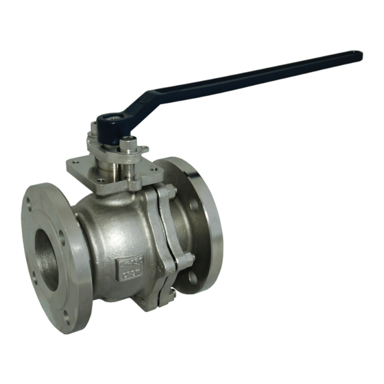
BALL VALVES
9100 SERIES
INSTALLATION, OPERATION
& MAINTENANCE MANUAL
This manual covers the installation, operation and maintenance of all AVCO standard 9100 series ball valves as
described in the current AVCO catalog. Custom made or customer modified versions of the 9100 series may
use this manual as a general guide only.
3210 S. Susan St, Santa Ana, CA 92704 Tel (714) 427-0877 Fax (714) 427-6392 Website: www.avcovalve.com
Advertisement
Table of Contents

Related Manuals for AVCO 9100 Series


Summary of Contents for AVCO 9100 Series
- Page 1 INSTALLATION, OPERATION & MAINTENANCE MANUAL This manual covers the installation, operation and maintenance of all AVCO standard 9100 series ball valves as described in the current AVCO catalog. Custom made or customer modified versions of the 9100 series may use this manual as a general guide only.
-
Page 2: General Design
Although the valves will operate with the handle or operator on the underside of the pipe it is not recommended and AVCO advises that, where possible, the valve handle be no more than from top dead center when installed in a horizontal pipe run, particularly when an actuator other than a manual handle is used. -
Page 3: Manual Operation
9100 SERIES Manual Operation All AVCO 9100 series ball valves are supplied with basic quarter turn lever handles as standard unless otherwise stated and no other lever should be used as a substitute or to create greater leverage. For all valve sizes there is a lock plate for valve lock-off which is achieved by inserting a padlock or other suitable locking device through the aligned holes. - Page 4 BALL VALVES 9100 SERIES 4 HOLES 4 HOLES TAPPED K TAPPED K 4 HOLES THRU THRU TAPPED K THRU PCD ØJ PCD ØJ PCD ØJ MOUNT PAD - 1/2" THRU 2 1/2" MOUNT PAD - 3" THRU 4" MOUNT PAD - 6" THRU 12"...
-
Page 5: Maintenance
1 below. Standard ISO brackets and couplers are available from AVCO to suit a wide range of actuator styles. AVCO advises, that where an actuator is used, the valve be installed as shown in fig. 1 and as described in paragraph 1.2 for optimal use and life span. - Page 6 Refurbishing AVCO Valves can be refurbished if the need arises and complete maintenance kits are available or individual components purchased as required. A maintenance kit consists of thrust ring, thrust seal, packing, Belleville washers, seats and body seals in quantities relevant to the specified valve size.
- Page 7 BALL VALVES 9100 SERIES 7.9.2 Remove the stem nut lock washer. 7.9.3 Use a wrench on the stem flats to prevent the stem from turning, unscrew the stem nut and remove. The Belleville washers, gland ring, travel stop (1/2” thru 1 1/4”) and packing can now be removed.
- Page 8 BALL VALVES 9100 SERIES required torque (see table 2) or until the Belleville washers are flattened. The Belleville washers should have their outside edges touching concentrically. The stem retainer ring can be inserted as soon as it is possible to do so.
- Page 9 BALL VALVES 9100 SERIES Bolting Information Stem nuts should be tightened finger tight and then torqued per table 2 or tightened with a wrench until the Belleville washers are fully flat. Once the required tightening has been achieved, the nut should be backed off no more than 1/8 turn until the lock pad can be assembled onto the stem.
- Page 10 BALL VALVES 9100 SERIES Sixteen bolt sequence 8.8.1 1st round to 20% torque - 1-2, 3-4, 5-6, 7-8, 9-10, 11-12, 13-14, 15-16 8.8.2 2nd round to 40% torque - 1-2, 3-4, 5-6, 7-8, 9-10, 11-12, 13-14, 15-16 8.8.3 3rd round to 80% torque - 1-2, 3-4, 5-6, 7-8, 9-10, 11-12, 13-14, 15-16 8.8.4...
-
Page 11: Safety Precautions
Any component that is replaced during maintenance or repair is an AVCO authorized spare part and is specific to the originally specified valve. Any component of the valve can be replaced, but AVCO recommends that if the body becomes damaged then the complete valve be replaced. - Page 12 BALL VALVES 9100 SERIES General Assemblies 11.1 The following figures show the typical general assemblies and materials for all valve sizes. ACTUATOR SET-UP 4 HOLES TAPPED K THRU PCD ØJ MOUNT PAD Fig. 5 - 1/2” thru 1 1/4” ACTUATOR SET-UP...
- Page 13 BALL VALVES 9100 SERIES ACTUATOR SET-UP 4 HOLES TAPPED K THRU PCD ØJ MOUNT PAD Fig. 7 - 3” thru 4” ACTUATOR SET-UP 4 HOLES TAPPED K THRU PCD ØJ MOUNT PAD Fig. 8 - 6” thru 12” 3210 S. Susan St, Santa Ana, CA 92704 Tel (714) 427-0877 Fax (714) 427-6392 Website: www.avcovalve.com...
- Page 14 Table 3 Copyright © 2010 Alloy Valves and Control Inc. All rights reserved. No part of this brochure may be used or reproduced in any manner whatsoever without written permission from AVCO This brochure is general in nature and we reserve the right to alter dimensions, materials or make design improvements.
Need help?
Do you have a question about the 9100 Series and is the answer not in the manual?
Questions and answers