Table of Contents
Advertisement
Quick Links
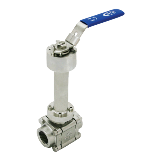
BALL VALVES
1500 SERIES
INSTALLATION, OPERATION
& MAINTENANCE MANUAL
This manual covers the installation, operation and maintenance of all AVCO standard 1500 series ball valves as
described in the current AVCO catalog. Custom made or customer modified versions of the 1500 series may
use this manual as a general guide only.
3210 S. Susan St, Santa Ana, CA 92704 Tel (714) 427-0877 Fax (714) 427-6392 Website: www.avcovalve.com
Advertisement
Table of Contents

Related Manuals for AVCO 1500 Series


Summary of Contents for AVCO 1500 Series
- Page 1 INSTALLATION, OPERATION & MAINTENANCE MANUAL This manual covers the installation, operation and maintenance of all AVCO standard 1500 series ball valves as described in the current AVCO catalog. Custom made or customer modified versions of the 1500 series may use this manual as a general guide only.
-
Page 2: General Design
The valves may be installed for uni-directional flow or vacuum and should only be installed in horizontal pipe runs. Please contact AVCO directly if a 1500 series valve has to be installed in a vertical pipe run. The valves must never be installed with the handle or operator on the underside of the pipe and AVCO... -
Page 3: Operation
NOTE: AVCO Supplies butt weld end caps in sch 10, sch 40 & sch 80 as standard and recommends that the adjoining pipe be the same schedule as that of the end cap to ensure an effective and even weld. -
Page 4: Manual Operation
Manual Operation All AVCO 1500 series ball valves are supplied with basic quarter turn lever handles as standard unless otherwise stated. For valve sizes up to 2” inclusive the lever has an integral stop for fully open and fully closed positions, there is also a sliding lockable tab to prevent accidental or unauthorized opening or closing of the valve. -
Page 5: Automated Operation
(across) the pipeline, then the valve is closed. Automated Operation These valves can be set up for automated operation as part of a process control system. AVCO supplies a large range of pneumatic and electric actuators with associated controls to accommodate most design conditions. -
Page 6: Maintenance
Standard ISO brackets and couplers are available from AVCO to suit a wide range of actuator styles. AVCO advises, that where an actuator is used, the valve be installed as shown in fig. 1 and as described in paragraph 1.2 for optimal use and life span. - Page 7 7.6.11 Operate the valve several times, re-check the bonnet bolt torques and tighten if required. Refurbishing AVCO Valves can be refurbished if the need arises and complete maintenance kits are available or individual components purchased as required. A maintenance kit consists of thrust washer, packing washers, seats and body seals in quantities relevant to the specified valve size.
- Page 8 BALL VALVES 1500 SERIES WARNING: Ball valves are designed as pressure containing equipment and as such a risk assessment should be carried out to ensure that no pressurized fluid or gas is contained in the ball cavity and relevant procedures followed for the handling of hazardous materials before any work commences.
- Page 9 BALL VALVES 1500 SERIES SOME SCORING/SCRATCHES PERMISSIBLE OUTSIDE SEATING ZONE Fig. 6 Ball Inspection 8.19 Remove the stem nut locking tab. 8.20 Use a wrench on the stem flats to prevent the stem from turning, unscrew the stem nut and remove. The disc spring washers, gland ring and packing can now be removed.
- Page 10 BALL VALVES 1500 SERIES 8.23 Insert the stem with thrust washer up into the valve body. 8.24 Ease the packing washers onto the stem whilst taking care not to damage them, followed by the gland ring and stop plate (2 1/2” thru 4”). Place the disc spring washers onto the stem whilst ensuring that the outside edges are touching concentrically.
- Page 11 AVCO holds spares in stock. Determining Correct Installation of Vented Ball 10.1 The 1500 series ball valve has a vented ball to prevent pressure build-up in the ball cavity and as such it is important the ball be correctly installed.
-
Page 12: Safety Precautions
11.1.4 Parts from other valve manufacturers must not be used. 11.1.5 If the valve is altered in any way from that of the original specification or without consent from AVCO, then no liability can be accepted by AVCO (Alloy Valves & Control). -
Page 13: Exploded Views
BALL VALVES 1500 SERIES 12.4 Wear protective headgear. 12.5 Wear protective footwear. 12.6 Ensure running water is easily accessible. 12.7 Have a suitable fire extinguisher nearby. 12.8 Check Upstream and downstream pressure gauges to ensure the pipeline contains no pressure. - Page 14 2 1/2” thru 4” Copyright © 2009 Alloy Valves and Control Inc. All rights reserved. No part of this brochure may be used or reproduced in any manner whatsoever without written permission from AVCO This brochure is general in nature and we reserve the right to alter dimensions, materials or make design improvements.
Need help?
Do you have a question about the 1500 Series and is the answer not in the manual?
Questions and answers