Table of Contents
Advertisement
Quick Links
BALL VALVES
1100 SERIES
INSTALLATION, OPERATION
& MAINTENANCE MANUAL
This manual covers the installation, operation and maintenance of all AVCO standard 1100 series ball valves as
described in the current AVCO catalog. Custom made or customer modified versions of the 1100 series may
use this manual as a general guide only.
3210 S. Susan St, Santa Ana, CA 92704 Tel (714) 427-0877 Fax (714) 427-6392 Website: www.avcovalve.com
Advertisement
Table of Contents

Related Manuals for AVCO 1100 Series


Summary of Contents for AVCO 1100 Series
- Page 1 INSTALLATION, OPERATION & MAINTENANCE MANUAL This manual covers the installation, operation and maintenance of all AVCO standard 1100 series ball valves as described in the current AVCO catalog. Custom made or customer modified versions of the 1100 series may use this manual as a general guide only.
-
Page 2: General Design
Although the valves will operate with the handle or operator on the underside of the pipe it is not recommended and AVCO advises that, where possible, the valve handle be no more than from top dead center when installed in a horizontal pipe run, particularly when an actuator other than a manual handle is used. -
Page 3: Operation
NOTE: AVCO Supplies butt weld end caps in sch 10, sch 40 & sch 80 as standard and recommends that the adjoining pipe be the same schedule as that of the end cap to ensure an effective and even weld. -
Page 4: Manual Operation
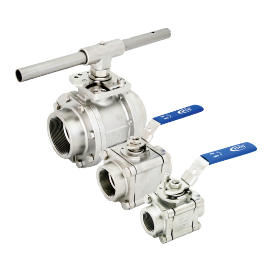
1100 SERIES Manual Operation All AVCO 1100 series ball valves are supplied with basic quarter turn lever handles as standard unless otherwise stated. For valve sizes up to 2” inclusive the lever has an integral stop for fully open and fully closed positions, there is also a sliding lockable tab to prevent accidental or unauthorized opening or closing of the valve. -
Page 5: Automated Operation
Standard ISO brackets and couplers are available from AVCO to suit a wide range of actuator styles. AVCO advises, that where an actuator is used, the valve be installed as shown in fig. 1 and as described in paragraph 1.2 for optimal use and life span. -
Page 6: Maintenance
Maintenance AVCO valves will give a long and trouble free life provided they are operated within the specified design parameters, but occasionally maintenance is required and should be addressed as set out below: Stem Leakage 7.2.1 Remove the handle/lever retaining nut or screw, handle/lever and locking tab. - Page 7 1100 SERIES Refurbishing AVCO Valves can be refurbished if the need arises and complete maintenance kits are available or individual components purchased as required. A maintenance kit consists of thrust washer, packing washers, seats and body seals in quantities relevant to the specified valve size.
- Page 8 BALL VALVES 1100 SERIES SOME SCORING/SCRATCHES PERMISSIBLE OUTSIDE SEATING ZONE Fig. 6 Ball Inspection 8.15 Ease the packing washers onto the stem whilst taking care not to damage them, followed by the gland ring and stop plate (2 1/2” thru 4”). Place the disc spring washers onto the stem whilst ensuring that the outside edges are touching concentrically.
- Page 9 BALL VALVES 1100 SERIES Bolting Information The stem nut should be tightened finger tight and then torqued per table 2 or tightened with a wrench until the disc spring washers are fully flat. Once the required tightening has been achieved, the nut should be further tightened no more than 1/4 turn until the lock pad can be assembled onto the stem.
-
Page 10: Safety Precautions
10.1.4 Parts from other valve manufacturers must not be used. 10.1.5 If the valve is altered in any way from that of the original specification or without consent from AVCO, then no liability can be accepted by AVCO (Alloy Valves & Control). -
Page 11: Exploded Views
Table 3 Copyright © 2009 Alloy Valves and Control Inc. All rights reserved. No part of this brochure may be used or reproduced in any manner whatsoever without written permission from AVCO This brochure is general in nature and we reserve the right to alter dimensions, materials or make design improvements.
Need help?
Do you have a question about the 1100 Series and is the answer not in the manual?
Questions and answers