
Related Manuals for CNH F5C


Summary of Contents for CNH F5C
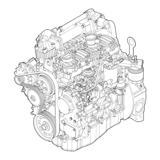
- Page 1 ENGINES F5C - F5A Structural and Non Structural Version ENGINES F5C - F5A Repair Manual Structural and Non Structural Version Tier III 4 Cylinders, Mechanical Print No. 87736548A English Repair Manual Tier III...
- Page 2 All the information, illustrations and data provided by this manual are based upon the most recent information available at the time of its publication. CNH ITALIA S.p.A. reserves the right to implement modifications, at any time, without communications. CNH ITALIA S.p.A.
- Page 4 - Please read carefully this manual for the correct CNH ITALIA S.p.A. information regarding the repair procedures. Strada Settimo, 323 San Mauro Torinese (TO) 10099 ITALIA PARTS &...
-
Page 5: Units Of Measure
IN- -2 FOREWORD UNITS OF MEASURE In this manual, the units of measure of the IS (International System) are used. The units of measure of the MKSA system are listed in parenthesis after the units of the International system. Example: 24.5 Mpa (250 kgf/cm Here below, a conversion table of the units of the IS and some units of measure of other systems is listed. -
Page 6: Special Remarks
F5 ENGINES SPECIAL REMARKS Diagrams and symbols have been widely used to give a clearer and more immediate illustration of the subject being dealt with, (see next page) instead of giving descriptions of some operations or procedures. Example ∅ Ø 1 = housing for connecting rod small end bush Tighten to torque Tighten to torque + angular value α... - Page 7 F5 ENGINES UPDATING Section Description Page Date of revision...
- Page 8 F5 ENGINES INTRODUCTION Introduction Page PREFACE TO USER’S GUIDELINE MANUAL ..SYMBOLS ....... - Warnings .
- Page 9 INTRODUCTION F5 ENGINES...
-
Page 10: Preface To User's Guideline Manual
F5 ENGINES INTRODUCTION PREFACE TO USER’S GUIDELINE MANUAL Manuals for repairs are split into Parts and Sections, each one of which is marked by a numeral; the contents of these sections are indicated in the general table of contents. The sections dealing with things mechanic introduce the specifications, tightening torque values, tool lists, assembly detaching/reattaching operations, bench overhauling operations, diagnosis procedures and maintenance schedules. - Page 11 INTRODUCTION F5 ENGINES Removal Intake Disconnection Refitting Exhaust Connection Removal Operation Disassembly Fitting in place ρ Compression ratio Assembly Tolerance Tighten to torque Weight difference Tighten to torque + angle value Rolling torque α Press or caulk Rotation Regulation Angle Adjustment Angular value Warning...
-
Page 12: General Warnings
F5 ENGINES INTRODUCTION GENERAL WARNINGS Warnings shown cannot be representative of all danger situations possibly occurring. Therefore, it is suggested to contact immediate superiors where a danger situation occurs which is not described. Use both specific and general-purpose toolings according to the prescriptions contained in respective use and maintenance handbooks. - Page 13 Before washing under pressure mechanical parts, protect electric connectors, and central units, if present. Tightening screws and nuts must always be according to prescriptions; CNH commercial and assistance network is available to give all clarifications necessary to perform repair interventions not provided in this document.
-
Page 14: General Warnings On The Electric System
Make sure that the electronic devices wiring harnesses (length, lead type, location, strapping, connection to screening braiding, bonding, etc.) comply with CNH system and are carefully recovered after repair or maintenance interventions. Measurements in drive electronic central units, plugged connections and electric connections to components can only be made on proper testing lines with special plugs and plug bushes. -
Page 15: Bonding And Screening
INTRODUCTION F5 ENGINES Bonding and screening Negative leads connected to a system bonded point must be both as short and possible and “star“-connected to each other, trying then to have their centering tidily and properly made (Figure 1, re. M). Further, following warnings are to be compulsorily observed for electronic components: Electronic central units must be connected to system bonding when they are provided with a metallic shell. - Page 16 F5 ENGINES INTRODUCTION OPTIONAL ELECTRICAL AND MECHANICAL PARTS INSTALLATIONS Assemblies shall be modified and equipped with additions - and their accessories shall be fitted - in accordance with the assembling directives issued. It is reminded that, especially about the electric system, several electric sockets are provided for as series (or optional) sockets in order to simplify and normalise the electrical intervention that is care of preparation personnel.
- Page 17 INTRODUCTION F5 ENGINES...
- Page 18 F5 ENGINES F5 ENGINES Section Part 1 F5CE Engines Part 2 F5AE Engines...
- Page 19 F5 ENGINES...
- Page 20 Thanks very much for your reading, Want to get more information, Please click here, Then get the complete manual NOTE: If there is no response to click on the link above, please download the PDF document first, and then click on it. Have any questions please write to me: admin@servicemanualperfect.com...
Need help?
Do you have a question about the F5C and is the answer not in the manual?
Questions and answers