Table of Contents
Advertisement
Quick Links
Advertisement
Table of Contents

Related Manuals for ROKAE XB10 Series


Summary of Contents for ROKAE XB10 Series
- Page 1 XB10 Series Pro d uc t Man u al...
- Page 3 XB10 Series Product Manual Document No.:DOC-0000386 Version: A © Copyright 2015 ROKAE. All rights reserved.
- Page 4 We will check the contents of this manual on a regular basis. No prior notice will be given if there is any change in the contents of the manual. It is impossible for ROKAE to foresee all hazards and consequences, and therefore this manual cannot warn the user of all possible hazards.
-
Page 5: Table Of Contents
2.4 Personnel and work content requirements ..................15 2.4.1 Definition of personnel ......................15 2.4.2 Personnel requirements ......................15 2.4.3 Work content requirements ...................... 16 2.5 Safety training ............................17 2.5.1 Overview ............................17 2.5.2 Personnel safety .......................... 17 XB10 Series Product Manual... - Page 6 5.5.3 Fixing the required parts ......................36 5.5.4 Bracket installation ........................37 5.5.5 Foundation installation ......................38 5.5.6 Supporting reaction force of the robot ...................39 5.6 Electrical connection ..........................40 5.6.1 Definition of the robot arm body side ports ................41 XB10 Series Product Manual...
- Page 7 7.3.5 Maintenance of timing belts ..................... 56 7.4 Cleaning ..............................59 7.5 Confirmation after maintenance ......................59 7.6 Maintenance Part List ..........................60 8 Common Failures ......................61 8.1 Introduction ..............................61 8.2 Analysis of the failure causes and countermeasures ................61 XB10 Series Product Manual...
-
Page 9: Manual Overview
For matters related to maintenance and repair of the robot, please contact our after-sales department or the local reseller. Service hotline: 400-010-8700. Get the following information ready when contacting us: Controller model/serial number Robot model/serial number Software name/version Problems with the system XB10 Series Product Manual... -
Page 11: Safety
2.1.1 Safety responsibility description ROKAE is dedicated to but not liable for providing reliable safety information. Even if all operations are carried out according to the safe operation instructions, we cannot guarantee that our industrial robots will not cause personal and property losses. -
Page 12: Hazard Description
During the maintenance and repair of the equipment, a burn may be caused if the maintenance personnel touch the surface robot's hot surface. Electric The current operation may cause an electric shock with a shock serious or even fatal injury. XB10 Series Product Manual... -
Page 13: Safety Features
The robot system is designed in accordance with the following relevant standards: Standard Description 2006/42/EC Machinery directive 2014/30/EU Electromagnetic compatibility directive EN ISO 12100:2010 Safety of machinery - General principles for design - Risk assessment and risk reduction XB10 Series Product Manual... -
Page 14: Motion Enabling And Safe Stop
Since the stop is controlled, in most cases, the robot will finally stop on the programmed path. Therefore, This emergency stop method provides the best protection for nearby equipment. Both safe stops arising from the opening of safety gate/safety grating in automatic mode XB10 Series Product Manual... -
Page 15: Safety Devices
Jog or run programs. Either releasing or pressing all the way down will cut off the motor power supply. XB10 Series Product Manual... -
Page 16: Safety Precautions
Therefore, one must observe the safety specifications when entering the working range of the robot. 2.3.1.2 About this section XB10 Series Product Manual... -
Page 17: About The User's Own Safety
Do not put the Teach Pendant cable on the edge of sharp objects, otherwise, the cable sheath may be damaged. Make sure that the bending radius of the Teach Pendant cable is greater than 100mm, otherwise, the cable may be damaged. 2.3.3.3 Permission of using the Teach Pendant XB10 Series Product Manual... -
Page 18: Safety Precautions For Using The Control Cabinet
The control cabinet cannot reach the claimed protection level when the cabinet door is open. When the cabinet door is open, components in the cabinet are more prone to electromagnetic interference and may generate excessive radiation to the outside, thus XB10 Series Product Manual... -
Page 19: Emergency Stop Button Test
2.3.7 Band-type brake test When the system enters the emergency stop state, the power source of the motors will be cut off and the band-type brakes of all joints will engage. Therefore, the normal operation XB10 Series Product Manual... -
Page 20: Manual Release Of The Band-Type Brake
2.3.9.1 About manual mode In manual mode, the motion of the robot is under manual control. Only when the enabling switch is in the middle position can you perform Jog or run programs on the robot. XB10 Series Product Manual... -
Page 21: Safety Precautions In Auto Mode
2.3.12 Safe handling of fire accidents 2.3.12.1 Measures against mild fire XB10 Series Product Manual... -
Page 22: Safe Handling Of Electric Shock Accidents
Call the wounded or pat him/her on the shoulder at an interval of 5 seconds to judge if he/she loses consciousness. Do not call the wounded by shaking his/her head. Meanwhile, contact the hospital as soon as possible. If the wounded loses consciousness, judge his/her respiratory conditions and XB10 Series Product Manual... -
Page 23: Personnel And Work Content Requirements
The operating personnel should understand applicable local safety regulations, such as the work safety and health regulations and the industrial accident prevention regulations. 2.4.2.2 Debugging personnel requirements The debugging personnel should meet the criteria of operating personnel. In addition, the XB10 Series Product Manual... -
Page 24: Work Content Requirements
When the power supply is switched on, some maintenance operations may pose the danger of electric shock. Switch off the power supply of the robot equipment and system before carrying out the maintenance. During the maintenance, prevent other personnel from switching on the power supply XB10 Series Product Manual... -
Page 25: Safety Training
Appropriate lighting should be provided during the maintenance. In case of part replacement, make sure to use a part specified by ROKAE. Otherwise, the robot equipment may be damaged. - Page 26 When servicing the interior of the control cabinet, if it is necessary to touch the power supply unit or printed circuit board, make sure to switch off the power supply of the main circuit breaker of the control cabinet first to prevent electric shock. XB10 Series Product Manual...
-
Page 27: Product Overview
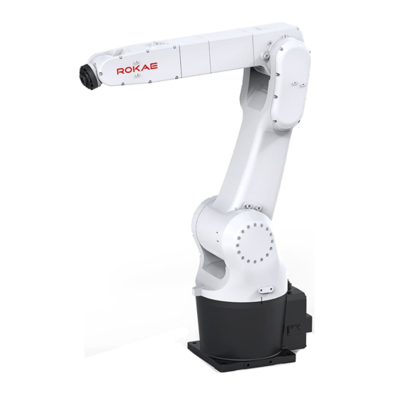
3 Product Overview 3 Product Overview 3.1 Introduction 3.1.1 Overview The XB10 series is a multi-configuration light-weight industrial robot product family with flexible configuration options to meet the requirements of diverse industrial application scenarios. 3.1.2 IP54 rating The XB10 product series has an IP54 protection rating configuration, which is achieved by adding dynamic and static seals and other accessories. -
Page 28: Robot Arm Body
Base - The base is the foundation of the entire robot, with the electrical interface of the robot arranged behind. Fig. 3 Movement direction of each axis Component name Wrist Upper arm Lower arm Swing joint Base 3.3 Symbols and labels XB10 Series Product Manual... - Page 29 Do not enter into the symbol working area while ! the robot is on, since the robot may collide and cause severe accidents. Packing and Indicates the packing transportation and transportation pose board pose of the product. XB10 Series Product Manual...
-
Page 31: Technical Specifications
Fig. 5 Model description 4.3 Specification Product name XB10 R1206 Driving mode AC servo Reach 1206mm Repeatability ±0.05mm Wrist payload 10kg Range of motion ±170° +125°~-95° +65°~-195° ±170° ±120° ±360° Maximum velocity 297°/s 223°/s 223°/s 480°/s 360°/s XB10 Series Product Manual... -
Page 32: Allowable Wrist Payload
The total weight of the end tooling fixture and workpiece should be less than the maximum payload of the robot. Make sure to match the load according to the robot's carrying capacity. The load exceeding the carrying capacity of the robot will trigger the XB10 Series Product Manual... -
Page 33: Center Of Gravity Of The Load
4.4.4 Calculating the Inertia Moment In order to ensure the best performance of the robot, it is necessary to make sure that the load (the weight of the end-effector and the workpiece) and the load inertia are within the XB10 Series Product Manual... -
Page 34: Working Space
The allowable inertia moment of XB10 series robots can be found in 4.4.1. Please calculate the inertia of the load before use and ensure that it is used within the allowable value. -
Page 35: Mounting Flange
Pay attention to the interference zone at the end of the fixture during design. The mounting flange of XB10 R1206 robots is shown in the figure below: XB10 Series Product Manual... - Page 36 4 Technical Specifications Fig. 10 Mounting flange XB10 Series Product Manual...
-
Page 37: Environment And Installation
Connect the I/O signal cable and air pipe 5.3 Environmental conditions The robot is suitable for general industrial environments, which should meet the following conditions: Item Condition Temperature 0°C~+40°C Relative humidity 20%~80%, no condensation Below ±2kV Electrical fast XB10 Series Product Manual... -
Page 38: Unpacking
Step 1: Open the wooden packaging box Put on a pair of protective gloves, cut off the metal packing straps of the wooden packaging box using a pair of steel strip scissors, and move the wooden box upwards to XB10 Series Product Manual... - Page 39 Use a pair of scissors to cut off the sealing tapes of the cardboard box, open the cardboard box, and take out the Teach Pendant cable, the Teach Pendant and the robot cable under the Teach Pendant foam. Fig. 12 Unpacking the control cabinet and the Teach Pendant cardboard box Name Teach Pendant XB10 Series Product Manual...
-
Page 40: Robot Transportation Angle
Handle the robot arm body carefully after removing the bolts. 5.4.2 Robot transportation angle XB10 Series Product Manual... -
Page 41: Inspection Before The Transportation
5.5 On-site installation 5.5.1 Handling 5.5.1.1 General description In principle, lifting equipment such as a traveling crane should be used during the handling. XB10 Series Product Manual... - Page 42 Fig. 15 shows the contour size of the robot in the transportation posture, in which dimensions C and D indicate the center of gravity position of the robot for reference in transportation. Fig. 15 Reference handling dimensions of the XB10 series Model A/mm...
- Page 43 Be careful not to tilt during the handling and transport slowly. XB10 Series Product Manual...
-
Page 44: Installing The Robot
When removing any screws from the robot equipment, hold the robot steady in order to prevent rollover; Retrofitting or disassembling the equipment is prohibited. If disassembly is necessary, please contact us. 5.5.3 Fixing the required parts XB10 Series Product Manual... -
Page 45: Bracket Installation
5.5.4 Bracket installation When the bracket installation method is selected, see the figure below for the reference bracket size for the XB10 R1206 base bracket installation: Fig. 18 Bracket fixing method XB10 Series Product Manual... -
Page 46: Foundation Installation
5.5.5 Foundation installation When the foundation installation method is selected, see the figure below for the installation and adaptation dimensions of XB10 R1206: Fig. 19 Foundation fixing method Description Adaptation plate Chemical bolt (expansion bolt) M20 Foundation XB10 Series Product Manual... -
Page 47: Supporting Reaction Force Of The Robot
The figure shows the force direction of the robot base. Name Description Fxy/N Force along any direction in the XY-plane Fz/N Force in the Z-plane Txy/Nm Bending torque along any direction in the XY-plane Tz/Nm Bending torque in the Z-plane XB10 Series Product Manual... -
Page 48: Electrical Connection
(e.g. do not turn on the power). Wiring when the power is on is extremely dangerous and may cause electric shock and/or failure of the robot system. Make sure that the equipment is properly grounded to avoid the risk of electric shock. XB10 Series Product Manual... -
Page 49: Definition Of The Robot Arm Body Side Ports
Reserv Reserv Reserved Reserv Reser A1-VC A2-VCC A3-VC A4-VC A5-VC A6-VCC Reserv Reser A1-GN A2-GND A3-GN A4-GN A5-GN A6-GND Reserv Reser A1-ES- A2-ES- A3-ES- A4-ES- A5-ES- A6-ES- Reserv Reser A1-ES+ A2-ES+ A3-ES+ A4-ES+ A5-ES+ A6-ES+ Reserv XB10 Series Product Manual... -
Page 50: Definition Of The Control Cabinet Side Ports
The power port definition table and signal port definition table on the control cabinet side are exactly the same as those on the robot arm body side. 5.6.3 Definition of the IO fitting pins Fig. 23 Definition of the IO fitting pins XB10 Series Product Manual... -
Page 51: Cabinet Cable Length And Wiring Method
Before wiring, power off the controller and related devices and place a warning symbol (e.g. do not turn on the power). Wiring when the power is on is extremely dangerous and may cause electric shock and/or failure of the robot system. XB10 Series Product Manual... - Page 52 It is recommended to use a M5,4-φ4,5bar circuit interface KQ2S04-M5A quick change fitting from SMC. Gas pipe plug M-5P Heavy-duty See 5.6.1 connector Pneumatic It is recommended to use a RC1/4,4-φ4,5bar circuit interface KQ2H04-01S direct fitting from SMC. XB10 Series Product Manual...
-
Page 53: Zero Calibration
Then calibrate each axis (just click the corresponding calibration button on HMI to record the multiturn value of the encoder), which can ensure that the zero position after calibration is exactly the same as the first mechanical XB10 Series Product Manual... -
Page 54: When Is Zero Calibration Required
Axis 6 zero point (please specify when ordering).It is recommended to design a 5(+0.02,+0.05)mm keyway on the end tool flange to cope with the calibration tool. Fig. 26 Calibration method Position XB10 Series Product Manual... -
Page 55: Mechanical Calibration
Only after the previous joint is moves to the zero position, click calibrated, can you click the "Calibrate" the "Calibrate" button for the button of the next joint. corresponding joint on the HMI and The joints with coupling relationship XB10 Series Product Manual... -
Page 56: Software Calibration
Log in to the system using an Zero calibration can only be performed admin-level or above user account in manual mode with no program and enter the zero calibration running. interface. The zero calibration interface is under the "Calibration" category. XB10 Series Product Manual... -
Page 57: Zero Check
(The robot can be moved to zero position quickly by using the HMI, see Fig. 30). If the robot cannot return to the correct zero position, please contact us. Fig. 29 Zero position of the robot XB10 Series Product Manual... - Page 58 6 Zero calibration Fig. 30 How to move to zero position XB10 Series Product Manual...
-
Page 59: Maintenance
Inspection items are carried out at five intervals: daily, one month, three months, six months and twelve months. Other items can also be added according to the intervals. 1) With the power OFF Item Position Interval Daily months months months months Check screws Externally ● for loosening visible screws XB10 Series Product Manual... - Page 60 Working space Each joint ● confirmation Check the whole robot Whole ● ● ● ● ● for abnormal sound robot and vibration Check for change in Whole ● positioning accuracy robot and deviation of the XB10 Series Product Manual...
-
Page 61: Lubrication
3) Clean the thread to prevent impurities from falling into the gearbox; 4) Refill an appropriate amount of grease into the wrist; 5) Apply an appropriate amount of thread sealant to the thread of the M10 screw plug, screw the M10 screw plug back(torque 6 Nm). XB10 Series Product Manual... -
Page 62: Fastening Of Socket Head Cap Screws
Socket head cap screw Torque (Nm) For the torque of the set screws used for the pulley, refer to the following table: Socket flat head set Torque (Nm) screw XB10 Series Product Manual... -
Page 63: Battery Replacement
Status confirmation: Only when the robot stays stationary and the power is OFF can you replace the battery. Check the status before operation. Warning A mechanical zero inspection should be performed upon the completion of battery XB10 Series Product Manual... -
Page 64: Maintenance Of Timing Belts
Step 7: Install the electrical installation board back. Tips When the zero point is lost due to failure to follow the above procedures, refer to 6.2. to carry out the zero calibration. 7.3.5 Maintenance of timing belts XB10 Series Product Manual... - Page 65 After replacement, conduct a zero calibration on the robot. If you have any problem during the adjustment, please contact ROKAE. Axes 3, 4, 5 and 6 of the robot are all driven by timing belts. If they become loosened, they may cause abnormal sound, accuracy decrease and other failures.
- Page 66 Loosen the flange fixing screws (a total of two, loosen them to an extent to which the pulley can move freely); Tighten the pulley by using a spring scale, and adjust the tension to the specified value; XB10 Series Product Manual...
-
Page 67: Cleaning
Do not clean the robot in case of incomplete robot appearance; Do not clean the robot with the power on. 7.5 Confirmation after maintenance Each time after performing maintenance operation on the robot, you should always confirm the robot status by following the procedures below: XB10 Series Product Manual... -
Page 68: Maintenance Part List
Width B=9mm 7.3.5.1 belt 14040300001 Width B=9mm 7.3.5.2 A5/A6 14040300002 Width B=6mm 7.3.5.3 Battery Base 15020301005/15070 Battery pack / 7.3.4 pack electrical 401332 Encoder battery installation component board Grease Wrist 19010100009 96 grease 7.3.2 (appropriate amount) XB10 Series Product Manual... -
Page 69: Common Failures
8.2 Analysis of the failure causes and countermeasures Possible failures of the robot are summarized in the table below. For those circumstances not mentioned in the list and for which causes cannot be identified, please contact ROKAE promptly. Failure... - Page 70 May be caused by wear of oil seal lip by impurities in extreme conditions; May be caused by improper sealing XB10 Series Product Manual...
- Page 71 The offset may be caused by motor encoder failure. Position offset after The origin may be Perform the zero parameter changes lost due to calibration again. parameter changes. XB10 Series Product Manual...
- Page 73 错误!文档中没有指定样式的文字。 Revision Version Date Content 2021/10/22 Initial version XB10 Series Product Manual...
- Page 75 [Back cover page]...
Need help?
Do you have a question about the XB10 Series and is the answer not in the manual?
Questions and answers