Table of Contents
Advertisement
Quick Links
Advertisement
Table of Contents

Subscribe to Our Youtube Channel
Related Manuals for ROKAE xMate SR3


Summary of Contents for ROKAE xMate SR3
- Page 1 SR3 Hardware Installation Manual A Partner You Can Rely on in Production...
- Page 2 SR3 Hardware Installation Manual Documet number: DOC-00001607 Version: D Copyright © ROKAE 2015-2023. All rights reserved.
- Page 3 This manual is originally written in Simplified Chinese. Other language versions are translated. Copyright © ROKAE 2015-2023. All rights reserved. ROKAE (Shandong) Intelligent Technology Co., Ltd. Shandong, China...
-
Page 5: Table Of Contents
2.5.7 Safe handling of electric shock accidents 2.6 Personnel and work content requirements 2.6.1 Definition of personnel 2.6.2 Personnel requirements 2.6.3 Work content requirements 2.7 Safety training 2.7.1 Overview 2.7.2 Personnel safety 2.8 Pre-use assessment 3 Product Overview ..........................16 3.1 Introduction xMate SR3 Hardware Installation Manual... - Page 6 6.2 Robot base 6.2.1 Robot power supply 6.2.2 Powering on the robot 6.2.3 Handheld emergency stop and enabling device interface 6.2.4 General-purpose DIDO 6.2.5 Safety DIO 6.2.6 Extended EtherNet interface 6.2.7 100-megabit Ethernet port on the base xMate SR3 Hardware Installation Manual...
- Page 7 8.1.2 What is a mechanical zero? 8.1.3 What is zero calibration? 8.1.4 When is zero calibration required? 8.2 Calibration method 8.2.1 Mechanical calibration 9 Decommissioning ..........................55 9.1 Robot decommissioning 9.2 Recycling Revision History ............................ 57 xMate SR3 Hardware Installation Manual...
- Page 9 1 Manual Overview DOC-00001607/D xMate SR3 Hardware Installation Manual...
-
Page 11: Manual Overview
Also, figures of other models may be used to describe some general information. 1.5 Related product documents This document is the product manual for the xMate SR3 robot and is intended to be used with the following documents: xCore Control System User Manual ⚫... -
Page 12: Safety
This section describes the principles and procedures that must be followed to ensure the safe use of the xMate SR3 robots. xMate SR3 robot integrators must read and understand the information listed here before powering on the robot for the first time. -
Page 13: Safety Notice
If you are unsure about the risks during the use of the robot, please contact ROKAE Technical Support. Problems arising from non-intended use are not covered by our support. -
Page 14: Emergency Stop Types
STOP0: The motor power is switched off and the brakes are engaged. STOP1: The robot comes to a controlled stop. Then the motor power is switched off and brakes are engaged. For xMate SR3 robots, STOP0 is used for handheld emergency stop signal processing. xMate SR3 Hardware Installation Manual... -
Page 15: Safety Precautions
The control system is built-in with three user levels, namely Operator, Admin, and God, with the operation permissions ranking from low to high. Switching from a low-privileged user to a high-privileged user requires a password. Otherwise, it is xMate SR3 Hardware Installation Manual... -
Page 16: Recovering From Emergency Stops
In Manual mode, signals of external safety devices such as the safety gate and safety grating will be bypassed. This means that the emergency stop will not be triggered in Manual mode even if the safety gate is open, which facilitates the debugging. 2.5.5 Safety precautions in Automatic mode xMate SR3 Hardware Installation Manual... -
Page 17: Safe Handling Of Fire Accidents
(CO2) fire extinguisher. 2.5.6.2 Treatment of severe fire disaster If the fire has spread and is beyond control, the workers on site shall notify other workers immediately to give up their personal belongings and evacuate immediately xMate SR3 Hardware Installation Manual... -
Page 18: Safe Handling Of Electric Shock Accidents
Operator The operating personnel can switch on/off the robot power supply and start robot programs through the Teach Pendant or other interfaces. Debugging personnel The debugging personnel can conduct robot operations, enter into the safeguarded xMate SR3 Hardware Installation Manual... -
Page 19: Personnel Requirements
2.6.2.3 Maintenance personnel requirements The maintenance personnel should meet the criteria of operating personnel. In addition, the maintenance personnel should also have a certain level of other xMate SR3 Hardware Installation Manual... -
Page 20: Work Content Requirements
During the maintenance, prevent other personnel from switching on the power ⚫ supply accidentally. To avoid unnecessary personal injury or adverse impact on the equipment, do ⚫ xMate SR3 Hardware Installation Manual... -
Page 21: Safety Training
Appropriate lighting should be provided during the maintenance. ⚫ In case of part replacement, make sure to use a part specified by ROKAE. ⚫ Otherwise, the robot equipment may be damaged. Parts removed during the replacement (such as screws) should be correctly ⚫... - Page 22 "under repair" sign in order to prevent other personnel from operating the equipment accidentally. Never enter into the working range of the robot while it is moving. ⚫ Never execute the automatic running of the program when there is other ⚫ xMate SR3 Hardware Installation Manual...
-
Page 23: Pre-Use Assessment
Test that the robot can switch between Manual and Automatic modes. ⚫ Test that the 3-position handheld emergency stop and enabling device must ⚫ be pressed to enable motion in Manual mode and that the robot is under reduced speed control. xMate SR3 Hardware Installation Manual... -
Page 24: Product Overview
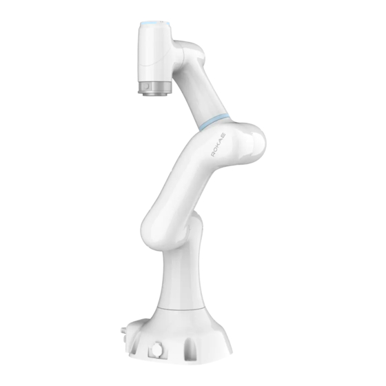
DOC-00001607/D 3 Product Overview 3.1 Introduction xMate SR3 is a next-generation flexible collaborative robot that features advanced force sensing and control capabilities, compact and lightweight design, and support for multiple communication protocols, making it an ideal solution in commercial scenarios such as robotic retail, robotic coffee, and robotic ice cream. -
Page 25: Definitions Of Rotation Directions And Coordinate Systems
Rotation axis directions: When the axes are in the zero position, the A1, A4 and A6 perform forward rotation in the +Z direction of the base coordinate system, the A3 and A5 in the -Y direction, and the A2 in the +Y direction. xMate SR3 Hardware Installation Manual... - Page 26 3 Product Overview DOC-00001607/D Flange coordinate system Base coordinate system Figure 3-2. Definitions of robot rotation directions and coordinate systems xMate SR3 Hardware Installation Manual...
-
Page 27: Symbols And Labels
Label type Remarks Arm body logo Product nameplate Indicates product model and other product information. Do not touch the electrical Electrical hazard components inside a live robot to symbol avoid the risk of electric shock. xMate SR3 Hardware Installation Manual... -
Page 28: Technical Specifications
4 Technical Specifications DOC-00001607/D 4 Technical Specifications 4.1 Introduction This section describes the specifications of the xMate SR3 flexible collaborative robot. 4.2 Specifications 4.2.1 Data sheet Product name xMate SR3 Number of axes Maximum reach 705 mm Repeatability ±0.02 mm... - Page 29 4 Technical Specifications DOC-00001607/D Maximum humidity for ≤ 90%, non-condensing, non-frost operation/storage xPad2 is Optional accessories for xMate SR3. xMate SR3 Hardware Installation Manual...
-
Page 30: Working Space
DOC-00001607/D 4.3 Working space The working space of xMate SR3 which mean the space skimmed by the wrist reference point (the intersection of the 4-axis and the 5-axis axis) is shown in the figure below: Figure 4-1. The working space of xMate SR3 4.4 Allowable load... -
Page 31: Allowable Wrist Torque And Inertia
Lxy represents the distance between the load center and the axis A6 and Lz represents the distance between the load center and the flange mounting surface. The distance corresponding to loads of different weights is shown in the following diagram. xMate SR3 Hardware Installation Manual... -
Page 32: Calculation Of Load Inertia
See 4.5.1 for the maximum allowable inertia of the xMate SR3 robots. Calculate the rotational inertia of the load before use and ensure that it is within the allowable range. - Page 33 4 Technical Specifications DOC-00001607/D xMate SR3 Hardware Installation Manual...
-
Page 34: Unpacking And Installation
DOC-00001607/D 5 Unpacking and Installation 5.1 Introduction This section contains instructions for unpacking and installing the xMate SR3 flexible collaborative robot. 5.2 Installation flow chart The installation flow chart is used to check the robot installation progress. Put a check mark in the "Completed"... -
Page 35: Unpacking And Hardware Installation
Protective gloves Unpacking procedures: ① Step 1: Open the packaging box Wear protective gloves and cut open the sealed package with scissors or a utility knife. You will find the following items in the box: xMate SR3 Hardware Installation Manual... - Page 36 Cable connecting base to teach pendant interface emergency stop enable handle USB drive xMate SR3 Quick Start Replaced by electronic file Guide Top liners xMate SR3 Power adapter Handheld emergency With cables stop & enabling device Bottom liners xMate SR3 Hardware Installation Manual...
-
Page 37: Robot Angle And Force Application Points During Transportation
It is strongly NOT recommended to apply force to other parts of the robot during transportation. 5.4.3 Check before installation Personnel who install and operate the robot must have the necessary knowledge for xMate SR3 Hardware Installation Manual... -
Page 38: On-Site Installation
In this case, the robot is unstable and moving the arms may displace or tilt the center of gravity, and even cause the robot to tip over. 5.5.1.2 Transportation dimensions xMate SR3 Hardware Installation Manual... - Page 39 5 Unpacking and Installation DOC-00001607/D Figure 5-3. Reference transportation dimensions of the robot xMate SR3 Hardware Installation Manual...
-
Page 40: Robot Installation
There are four M6 threaded holes on the wrist flange of the robot to attach the tool to the flange. The M6 bolts must be tightened with a torque of 15.6 Nm. See the figure below for the detailed dimensions. xMate SR3 Hardware Installation Manual... -
Page 41: Power Adapter
The location must meet the following conditions: With good ventilation and heat dissipation conditions; Outside the range of motions of xMate SR3; The power switch is easy to access for operators. xMate SR3 Hardware Installation Manual... -
Page 43: Electrical Connections
SR4 robot Handheld emergency stop and enabling device External network External power supply Power adapter Notes For information on how to control and use the xMate robot, see the user manual of the robot software. xMate SR3 Hardware Installation Manual... -
Page 44: Robot Base
(hole-type) to supply power to the robot. The electrical specifications of the power supply of the robot are shown below. Parameter Typical Unit Input voltage 43.2 52.8 range Power range —— 1000 xMate SR3 Hardware Installation Manual... -
Page 45: Powering On The Robot
SR4 provides 4 digital input and 4 digital output channels on terminal connector J3. Users must connect to the corresponding channel using a cable with the E0308 pin- type cold-pressed terminal in order to use the DIO function. xMate SR3 Hardware Installation Manual... - Page 46 Typical Unit Input voltage range The electrical principles in the two modes are shown below. PNP input See Figure 6-6 for details on a PNP configuration. xMate SR3 Hardware Installation Manual...
- Page 47 If the continuous load current exceeds the limit, an additional relay will be required to drive the system. The electrical principles in the two modes are shown below. NPN output Connect the DO_COM end to the negative terminal of the power supply, as shown in Figure 6-8. xMate SR3 Hardware Installation Manual...
-
Page 48: Safety Dio
All safety DIOs are redundant in pairs and must be kept as two independent branches so that a fault on one branch will not cause the failure of the safety function. Point position Definition SGATE1 SGATE1 SGATE2 SGATE2 EXSTOP1 EXSTOP1 EXSTOP2 xMate SR3 Hardware Installation Manual... - Page 49 Be sure to check the safety functions before putting the robot into operation. The safety functions must be checked regularly. The robot must be installed in compliance with these specifications. Failure to do so could result in serious injury or xMate SR3 Hardware Installation Manual...
-
Page 50: Extended Ethernet Interface
6.2.8 EtherCAT servo drive debug interface M12 is a round connector that can be connected by a dedicated extension cable. It allows for servo parameter setting and status monitoring, which are only available to internal debugging professionals. xMate SR3 Hardware Installation Manual... -
Page 51: Function Buttons And Interfaces On The Wrist
6.2.9.1 End effector 100-megabit Ethernet port(Optional accessories) Adjacent to the tool flange on the robot wrst, a round connector is equipped to connect to the 100-megabit Ethernet port on the base, providing the robot's end xMate SR3 Hardware Installation Manual... - Page 52 It can be used with the user-specific connector M8-FS-8CON-PVC-2.0. Figure 13. The end effector round connector interface Color Definition White DI_0 Brown DI_1 Green DO_0 xMate SR3 Hardware Installation Manual...
- Page 53 NPN type Default Activated Unit Output level Suspended —— —— Continuous —— load current PNP type Default Activated Unit Output level Suspended V_OUT —— —— Continuous —— load current Figure 14. End effector output interface xMate SR3 Hardware Installation Manual...
-
Page 54: Power Adapter
Attention: The analog inputs in the tool are not current/voltage-limited. Overriding the specifications can cause permanent damage. 6.3 Power adapter The power adapter is an optional accessory of the xMate robot, which converts the mains to the DC power usable by the robot. xMate SR3 Hardware Installation Manual... -
Page 55: Power-On Button Of The Power Adapter
20 to 90% RH, non-condensing humidity Storage -40 to +85°C, 10 to 95% RH temperature and humidity Vibration 10 to 500 Hz, 2G 10 min/cycle, 60 resistance min for each of the X, Y, and Z axes xMate SR3 Hardware Installation Manual... -
Page 56: Teach Pendant(Optional Accessories)
48V DC voltage usable by the xMate robot. It works with the xMate power cord that has a special-purpose plug (pin-type) to supply power to the robot. Figure 18 Power output interface 6.4 Teach Pendant(Optional accessories) 6.4.1 Teach Pendant buttons Fig 6-23 Teach Pendant buttons xMate SR3 Hardware Installation Manual... -
Page 57: How To Hold The Teach Pendant
Teach Pendant with left hand and operate the buttons and touch screen with right hand. It is recommended to hold the Teach Pendant in the way shown in the figure below: Fig 6-24 How to hold the Teach Pendant xMate SR3 Hardware Installation Manual... -
Page 58: Maintenance
7.4 Check Interval Item Position Daily month months months months Check the Robot √ appearance appearance for any External √ damage. cables Check the Robot base √ power adapter and Power √ the robot adapter base xMate SR3 Hardware Installation Manual... -
Page 59: Cleaning
Do not apply excessive force to the manipulator during cleaning. Always hold the part that is manually cleaned by hands to avoid overloading the manipulator and causing any damage. Power on the robot only after all the surfaces are completely dry. Warning Improper cleaning may damage the robot. xMate SR3 Hardware Installation Manual... -
Page 61: Zero Calibration
8.1.4.2 When the multi-turn counter data of the encoder is lost A zero calibration can be performed using dedicated calibration tools in the following circumstances: After reinstalling the entire hard disk system; ⚫ After replacing the encoder battery. ⚫ xMate SR3 Hardware Installation Manual... -
Page 62: Calibration Method
Figure 19. Step 1 Step 2: calibrate the second, third, fifth and sixth axis Calibrate according to step 1. Warning After the mechanical zero calibration is over, be sure to check the robot body status to prevent accidents. xMate SR3 Hardware Installation Manual... -
Page 63: Decommissioning
DOC-00001607/D 9 Decommissioning 9.1 Robot decommissioning The decommissioning, storage and disposal of the robot must be performed in compliance with relevant national laws, regulations, and standards. 9.2 Recycling Contact us for the recycling of batteries. xMate SR3 Hardware Installation Manual... -
Page 65: Revision History
2. Modify the range information 3. Section 5.4.1: Supplementary information about unpacking materials 2023/8/23 1. Update 2 Safety. 2. Update doc-num and version 3. Update 4.2 specification 4. Add 4.4 Allowable load 2023/9/25 1. Update 5.4.1 2. Update 7.4 xMate SR3 Hardware Installation Manual... - Page 67 ROKAE...
Need help?
Do you have a question about the xMate SR3 and is the answer not in the manual?
Questions and answers