Table of Contents
Advertisement
Quick Links
OWNER`S MANUAL
Escape 1400-I Insert
US ENVIRONMENTAL PROTECTION
AGENCY PHASE II CERTIFIED
WOOD INSERT
Verified and tested following
ULC S628 and UL 1482 Standards
by:
Manufactured by : STOVE BUILDER INTERNATIONAL INC..
1700, Léon-Harmel, Québec (Québec) G1N 4R9
Tel : (418 ) 527-3060
Fax : (418 ) 527-4311
www.drolet.ca
READ AND KEEP THIS MANUAL FOR REFERENCE
45221
Advertisement
Table of Contents

Related Manuals for STOVE BUILDER INTERNATIONAL INC Drolet Escape 1400-I


Summary of Contents for STOVE BUILDER INTERNATIONAL INC Drolet Escape 1400-I
- Page 1 AGENCY PHASE II CERTIFIED WOOD INSERT Verified and tested following ULC S628 and UL 1482 Standards Manufactured by : STOVE BUILDER INTERNATIONAL INC.. 1700, Léon-Harmel, Québec (Québec) G1N 4R9 Tel : (418 ) 527-3060 Fax : (418 ) 527-4311 www.drolet.ca...
-
Page 2: Introduction
INTRODUCTION SBI INC., one of the most important wood stove and fireplace manufacturers in Canada, congratulates you on your purchase and wishes to help you get maximum satisfaction from your wood insert. In the pages that follow, we will give you advice on wood heating and controlled combustion as well as technical specifications regarding installation, operation and maintenance of the model you have chosen. -
Page 3: Table Of Contents
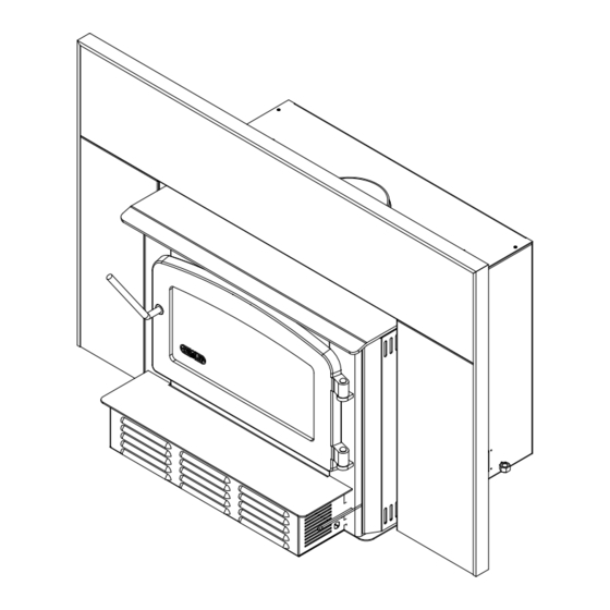
TABLE OF CONTENTS INTRODUCTION ..............................1 Section 1.0 Pre-Installation Requirements ......................4 1.1 Masonry & Zero Clearance Requirements ....................4 1.2 Venting Requirements ...........................5 Section 2.0 Installation .............................6 2.1 Clearances To Combustibles (Measured From Insert Body) ..............6 2.1.1 Hearth Requirements ..........................7 2.2 Suitable Fireplace Dimensions ........................7 2.3 Safety Information ............................8 2.4 Installation Instructions ..........................9 2.5 Air control plate, faceplate and fan Assembly Instructions ..............10... - Page 4 Escape 1400-I Dimensions 28 25/64" 26 29/32" 13 29/64" 6.000" 13 3/8" 15 1/32" 8 9/64" 6 31/64" 20 31/32" 20 31/32" 8 9/32" 9 61/64" Faceplate fully extended toward the back Faceplate fully extended toward the front...
-
Page 5: Section 1.0 Pre-Installation Requirements
Section 1.0 Pre-Installation Requirements 1.1 Masonry & Zero Clearance Requirements The masonry fireplace must meet the minimum code requirements, or NFPA 211 or the equivalent for a safe installation. Contact your local Building Inspector for requirements in your area. An inspection of the fireplace should include the following: 1. -
Page 6: Venting Requirements
1.2 Venting Requirements The flue is a critical component to a satisfactory installation. Your Drolet insert will attain its best performance if installed with a chimney that generates its own draft. The minimum requirement of a flue will be the installation of a flue connector (the liner must conform to UL1777 chimney liners) from the insert into the first flue tile of the chimney (USA), see Figure 2.3 , or a continuous stainless steel liner (the liner must conform to the Class 3 requirements of CAN/ULC-S635) directly connected to the flue outlet (Canada), see Figure 2.2. -
Page 7: Section 2.0 Installation
Section 2.0 Installation 2.1 Clearances To Combustibles (Measured From Insert Body) Escape 1400-I Sidewall (A) 13” (330 mm) Shelf (B) 22” (559 mm) Side mantle (C) 10” (254 mm) Top mantel (D) 29” (737 mm) Table 2.1 CLEARANCES Figure 2.1 Note: If side mantle protrudes more than 1.5”... -
Page 8: Hearth Requirements
2.1.1 Hearth Requirements If the non-combustible hearth is flush with the floor, then the hearth must be 16”/406mm (18”/450mm in Canada) in front of the fan housing (see Figure 2.1.2). If the non- combustible hearth is a minimum of 4” (102mm) above the floor, then the hearth can be 6” (152mm) out from the fan housing with a 10”... -
Page 9: Safety Information
2.3 Safety Information NOTE: This appliance is not recommended for use in a home if an occupant has any respiratory or any other related problems. 1. It is important to follow the installation and operation instructions. An improperly installed or operated insert could result in a safety hazard or fire, or damage to the unit, which would not be covered by the warranty. -
Page 10: Installation Instructions
2.4 Installation Instructions 1. Inspect the fireplace according to the safety information and fireplace requirements and have it cleaned and/or upgraded as necessary. 2. If the installation of the unit renders the existing damper control inaccessible, it will be necessary to either secure the damper wide open or remove it entirely. -
Page 11: Air Control Plate, Faceplate And Fan Assembly Instructions
2.5 Air control plate, faceplate and fan Assembly Instructions 1. Place the faceplate panels with the finished side down on a flat, soft, non-abrasive surface. 2. Assemble the faceplate trim, attaching the mitered corners with the corner brackets. (see Figure 2.4) 3. -
Page 12: Safety Information
3.1 Safety Information This insert is designed for safe operation . Altering or modifying URNING ORDWOOD the unit or the installation without proper authorization will void the certification, warranty, and safety listing, and may result in a safety hazard. For safety reasons, never leave the unit unattended with the door open or ajar. An open door, and especially a door partially open or cracked, if left for longer than required for good ignition can potentially result in unsafe chimney temperatures, and if left unattended, hot embers or ignited fuel may fall out of the unit. -
Page 13: Fuel
homes, could possibly cause smoke spillage into the room. Smoke may contain carbon monoxide, which is poisonous, and in sufficient quantities is a health hazard. 11. We recommend that you have a fresh air or make up air supply for the insert. In Canada this is a building code requirement. -
Page 14: Simple Wood Moisture Test
For recommended wood sizes, refer to the specifications. Common Heating Values of Cordwood Hardwoods Million Btu/Cord Softwoods Million Btu/Cord Birch 23.6 Douglas Fir 20.6 White Oak 28.3 Hemlock 17.1 Alder 17.6 Jack Pine 18.4 Table 3.1 3.2.1 Simple Wood Moisture Test Add one large piece of wood to the top of an established fire. - Page 15 established. Once the firebox is hot, the draft control can be partially closed by moving the knob to the left to adjust the intensity of the fire. Use Table 3.2 to adjust the draft control to the desired burn rate: Draft Settings Burn Rate Draft Setting...
-
Page 16: Maintaining The Fire
3.5 Maintaining The Fire Your Drolet insert will work best if a thick bed of hot embers is maintained in the bottom of the firebox, and a minimum of two large pieces of seasoned fuel are added. Combustion efficiency is largely related to establishing a hot ember bed, and hot firebox temperatures. -
Page 17: Section 4.0 Maintenance
Section 4.0 Maintenance 4.1 Care And Cleaning Clean the insert frequently so that soot, ash and creosote do not accumulate. Do not attempt to clean the insert, glass or door when the unit is hot. Special care must be taken with plated surfaces in order to maintain the finish at its original brilliance. -
Page 18: Chimney Cleaning
CAUTION: Ashes can start fires, even after several days of inactivity. Never dispose of ashes in a combustible container. Remove ashes only when the insert and ashes are cold. Ashes should be removed from the insert frequently. When ashes are removed, they should be placed in a metal container with a tightly fitting lid. -
Page 19: Baffle Installation For Escape 1400-I
4.4 Baffle Installation for Escape 1400-I WOOL WEIGHT INSULATION BLANKET VERMICULITE BAFFLE BOARD MIDDLE AND REAR TUBES FRONT TUBE FRONT BAFFLE SUPPORT Figure 4.1 – Baffle installation & removal for Escape 1400-I The baffle assembly must be properly in place for correct burning operation. Have any damaged firebricks replaced. -
Page 20: Secondary Air Tube Replacement
4.5 Secondary Air Tube Replacement (see Figure 4.3) Remove cotter pin at RH end of tube. Slide tube to left and lower tube end below RH plenum. Slide tube to right to remove. Reassemble in reverse order using a new cotter pin. The cotter pin is a hammerlock style and locks into place by hitting the head sharply with a hammer. -
Page 21: Fan Maintenance & Care
Figure 4.3 – Secondary Air Tube replacement 4.6 Fan Maintenance & Care Clean the fan air inlet louvres and squirrel cage impeller regularly. The fan should be kept clean and dust free. Life of the fan will be shortened if operated in a dust filled environment, or if the fan is overheated by restricting air supply. -
Page 22: Section 5.0 Specifications
Section 5.0 Specifications 5.1 Escape 1400-I Insert Model Fuel Type Cordwood Test Standards ULC S628 (CSA B366.2) & UL 1482 residential. Heat Output Max of 39000 BTU/Hr with EPA test wood BTU/Hr (63% default efficiency) Range Will vary with usage depending on the type and condition of cord wood. Shipping Weight 370lbs (168kg) Firebox Volume... -
Page 23: Drolet Limited Lifetime Warranty
DROLET LIMITED LIFETIME WARRANTY The warranty of the manufacturer extends only to the original consumer purchaser and is not transferable. This warranty covers brand new products only, which have not been altered, modified nor repaired since shipment from factory. Proof of purchase (dated bill of sale), model name and serial number must be supplied when making any warranty claim to your DROLET dealer.
Need help?
Do you have a question about the Drolet Escape 1400-I and is the answer not in the manual?
Questions and answers