
Related Manuals for Tonghui Electronics TH1991


Summary of Contents for Tonghui Electronics TH1991
- Page 1 TH1991/1992 Precision Source/Measure Unit Tonghui Electronic Co.,Ltd. www.tonghui.com.cn...
- Page 2 Version History: This manual will be continuously improved to facilitate the use. Due to possible errors or omissions in the manual, improvement and refinement of instrument functions, technical updates and software upgrades, the manual will be adjusted and revised accordingly. Please pay attention to the software version and manual version you are using.
-
Page 3: Table Of Contents
TH1991/1992 User Manual V1.1 Contents Table of Contents Chapter 1 Overview ........................1 1.1 Introduction ..........................1 1.2 General Specifications ......................... 1 1.2.1 Power Supply ........................1 1.2.2 Environment / Temperature / Humidity / Altitude ............... 2 1.2.3 Warm-up ..........................2 1.2.4 Volume and Weight ...................... - Page 4 TH1991/1992 User Manual V1.1 Contents 3.2.1 Source Specification ......................2 3.2.2 Output Specification ......................6 3.2.3 Measurement Specifications ....................12 3.2.4 Trigger and Timing Specifications ..................16 Chapter 4 Function Instructions ....................1 4.1 Basic Operation ........................... 1 4.2 Display Screen Description ......................1 4.2.1 Home Show Page .........................
- Page 5 TH1991/1992 User Manual V1.1 Contents 6.2 Symbol Conventions and Definitions ..................4 6.2.1 Symbols ..........................4 6.2.2 Suffix Numbers ........................5 6.2.3 Channel List Parameters ....................... 5 6.3 Data Output Format ........................5 6.4 Command Reference ........................6 6.4.1 DISPlay Subsystem Command ..................... 7 6.4.2 FORMat Subsystem Command ....................
-
Page 6: Chapter 1 Overview
1.1 Introduction TH1991/TH1992 is a series of precision source/measure units, referred to as SMU. It offers touch screen, front panel keys and knobs to apply voltage/current or measure voltage/current/resistance. -
Page 7: Environment / Temperature / Humidity / Altitude
TH1991/1992 User Manual V1.1 Chapter 1 Overview 1.2.2 Environment / Temperature / Humidity / Altitude Environment: suitable for indoor equipment use Operation status: Temperature: 0℃ to +55℃ Humidity: 30% to 80% RH (no condensation) Altitude: 0~2000m (6561ft) ... -
Page 8: Safety Standards
TH1991/1992 User Manual V1.1 Chapter 1 Overview 1.3 Safety Standard This instrument is a Class I safety instrument EMC Standard: IEC61326-1/EN61326-1/AS/NZS CISPR 11 1.3.1 Insulation Resistance The insulation resistance between the power supply terminals and the housing is not less than 50MΩ under reference operating conditions. -
Page 9: Chapter 2 View Description
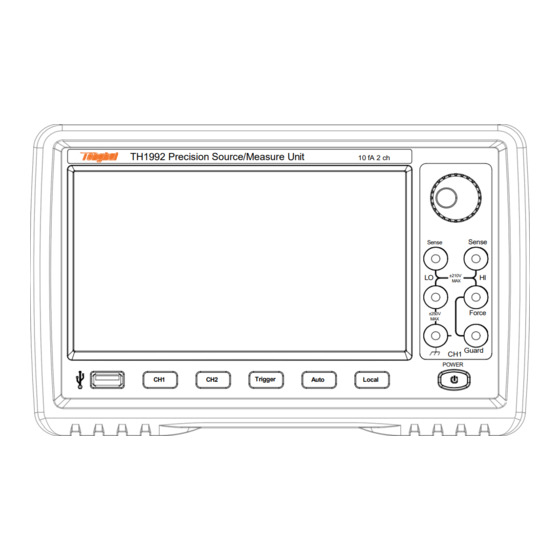
TH1991/1992 User Manual V1.1 Chapter 2 View Description Chapter 2 View Description The content of this chapter is only a general description; the specific operation and detailed explanation refer to the corresponding content of Chapter 4. 2.1 Front Panel Description... -
Page 10: Rear Panel Description
TH1991/1992 User Manual V1.1 Chapter 2 View Description Auto: Starts a repeat measurement. Stops repeated measurements if they are being performed. Local: If the instrument is in the remote state, return it to the local state Line switch: Turns the instrument on and off. -
Page 11: Page Summary
TH1991/1992 User Manual V1.1 Chapter 2 View Description Channel 2 source/measurement terminals: For 2-channel models only, High Force, Low Force, High Sense, Low Sense, Guard, and Chassis Ground. (See 5.1 Measurement Terminals) Cooling fan: Forced ventilation to avoid internal temperature rising and affecting accuracy. -
Page 12: Config Page
TH1991/1992 User Manual V1.1 Chapter 2 View Description for channel 2. Each area displays the measurement results, the source, and the measurement settings. The parameters that can be set are as follows: Source: Source function, voltage source VOLTs (V) or current source AMPs (I). -
Page 13: Quick I/V Page
TH1991/1992 User Manual V1.1 Chapter 2 View Description Filter Setup: Filter Setup. Relative offset: The relative offset setting. Math Function: Math operation function setting. Limit tests: Limit test setting. 2.3.3 Quick I/V Page Figure 2-5 Quick I/V Page The Quick I/V page mainly displays the Graph and Roll views. -
Page 14: File Page
TH1991/1992 User Manual V1.1 Chapter 2 View Description The Expert page is the graphical analysis of semiconductor parameters, which is the advanced function and contains the following test functions: Diodes: Diode Testing FETs: Field Effect Transistor Testing ... - Page 15 TH1991/1992 User Manual V1.1 Chapter 2 View Description Figure 2-8 System Page RS232/GPIB: Serial/GPIB communication setting Usb device: USB setting Network: Network setting Digital I/O: Input/output pin setting User Setup: User setup Date Time: Device date and time setting ...
-
Page 16: Chapter 3 Basic Technical Specifications
3.1.2 Limit / Compliance The TH1991/TH1992 has the compliance function that limits the output voltage or current to prevent damage to the device under test. When the SMU applies voltage, the current limit/compliance can be specified. When the SMU applies current, the voltage limit/compliance can be specified. -
Page 17: Technical Specifications
3.2 Technical Specifications This chapter lists specifications features TH1991/TH1992 series. The specifications are based on the standards that test TH1991/TH1992, and the requirements which they conform at the factory. 3.2.1 Source Specifications 3.2.1.1 Voltage Sources Programming Resolution Noise (peak-... - Page 18 TH1991/1992 User Manual V1.1 Chapter 3 Basic technical specifications ≤200uV ± 20V 100uV 100uV 10uV ± (0.015%+5mV) ± 21V ≤2mV ± 200Vb 100uV ± (0.015%+50mV) ± 210V Table 3-1 Voltage Source Specifications *Note: Superscript a: Additional features Voltage limit/compliance: Accuracy is the same as the voltage source.
- Page 19 TH1991/1992 User Manual V1.1 Chapter 3 Basic technical specifications ± (0.02%+25 ≤3nA ± 100uA 100pA ± 105uA ± (0.02%+20 ≤6nA ± 1mA 10nA 10nA ± 1.05mA 0nA) ± (0.02%+2. ≤200nA ± 10mA 100nA 100nA 10nA ± 10.5mA 5uV) ± (0.02%+20 ≤600nA...
- Page 20 TH1991/1992 User Manual V1.1 Chapter 3 Basic technical specifications Superscript b: ± 10nA does not apply to TH1991A/C and TH1992A. Superscript c: ± 100nA is not applicable to TH1991C. Superscript d: ± 3A, ± 10A do not apply to TH1991B/C and TH1992B.
-
Page 21: Output Specification
TH1991/1992 User Manual V1.1 Chapter 3 Basic technical specifications Source Stabilization Minimum Pulse Source Value Limit Value Load (% of range) Width 200Ω 200V 1.5A 0.1% 0.6Ω 10.5A 0.1% 0.2ms 65Ω 1.5V 200V 0.1% 2.5ms 0.5Ω 10.5V 0.1% 0.2ms Table 3-4 Minimum Pulse Width for Given Voltage and Current with Stability Condition ※Note:... - Page 22 TH1991/1992 User Manual V1.1 Chapter 3 Basic technical specifications Figure 3-3 Output Range Total Current Limit When Using Channel 1 (I1, Maximum Maximum V1) and Channel 2 (I2, V2) Voltage in V Current in A V1 in V V2 in V Current Limit in A ±(0≤V2≤6)
- Page 23 TH1991/1992 User Manual V1.1 Chapter 3 Basic technical specifications Table 3-5 Maximum Voltage and Current Maximum Set Resolution Current Voltage Measurement Pulse Output Range Value Width TH1991B TH1991A TH1991 Value Pulse TH1991C Output Output TH1992B TH1992A TH1992 0≤|V| 0.2V 0.1uV ≤0.21V...
- Page 24 TH1991/1992 User Manual V1.1 Chapter 3 Basic technical specifications Maximum Set Resolution Voltage Current Measurement Pulse Output Range Value Width TH1991B TH1991A TH1991 Value Pulse TH1991C Output Output TH1992B TH1992A TH1992 0≤|I|≤ 10nA 100fA 10fA 10.5nA 0≤|I|≤ 100nA 10pA 100fA 105nA 0≤|I|≤...
- Page 25 TH1991/1992 User Manual V1.1 Chapter 3 Basic technical specifications 1.515A 50us 0≤|I|≤ ≤t≤ ± 21V 1.515A 100ks 50us 0≤|I|≤ ≤t≤ ± 180V 1.05A 10ms 50us 0≤|I|≤ ≤t≤ ± 200V 1.515A 2.5ms 0≤|I|≤ ± 210V 105mA 105mA ≤|I|≤ ± 21V 100uA 1.515A...
- Page 26 TH1991/1992 User Manual V1.1 Chapter 3 Basic technical specifications Normal mode: 0.01uF High capacitance mode: 50uF DC floating voltage: ± 250V DC maximum between low voltage and chassis ground Protection offset voltage (V source): <4mV ...
-
Page 27: Measurement Specifications
TH1991/1992 User Manual V1.1 Chapter 3 Basic technical specifications Delay beyond high capacitance mode: all ranges: 10ms Noise 10Hz to 20MHz (20V range): 50mVrms Voltage source range change overshoot (20V range or less): ≤250mV, 20MHz bandwidth ... - Page 28 TH1991/1992 User Manual V1.1 Chapter 3 Basic technical specifications 0≤|I|≤10.6uA ± 10uA 10pA 10pA ± (0.025%+1.5nA) 0≤|I|≤106uA ± 100uA 100pA 100pA ± (0.02%+25nA) 0≤|I|≤1.06mA ± 1mA ± (0.02%+200nA) 0≤|I|≤10.6mA ± 10mA 10nA 10nA ± (0.02%+2.5uV) 0≤|I|≤106mA ± 100mA 100nA 100nA ±...
- Page 29 TH1991/1992 User Manual V1.1 Chapter 3 Basic technical specifications and Table 2-8. Source V mode, manual ohmic measurement (4-wire): Total error=V =1/ [1/R reading*(gain error of I range + gain source measure error of V range + offset error of V range/V source*100) %+ (offset error of...
- Page 30 TH1991/1992 User Manual V1.1 Chapter 3 Basic technical specifications Current Total Error (% reading + Range Value Display Resolution Test Current Range offset) 2Ω 1uΩ 0.02%+0.00035Ω 20Ω 10uΩ 0.006%+0.0035Ω 100mA 100mA 200Ω 100uΩ 0.065%+0.035Ω 10mA 10mA 2kΩ 1mΩ 0.06%+0.35Ω 20kΩ...
-
Page 31: Trigger And Timing Specifications
Timer accuracy: ± 50ppm Switch on/trigger delay: 0 to 100,000s Switch on/trigger interval: TH1991/TH1992: 20us to 100,000s TH1991A/TH1992A: 10us to 100,000s TH1991B/TH1992B: 200us to 100,000s TH1991C: 50us to 100,000s Switch on/trigger event: 1 to 100,000 ... -
Page 32: Chapter 4 Function Instructions
TH1991/1992 User Manual V1.1 Chapter 4 Feature Usage Notes Chapter 4 Function Instructions 4.1 Basic Operation The basic operation of the instrument is described below. Use the touch screen to click on the main menu on the right to access the desired main page. - Page 33 TH1991/1992 User Manual V1.1 Chapter 4 Feature Usage Notes displays the output and measurement results along with a number of settable parameters: Source type (Source), Voltage range (V-range), Current range (I-range), Source output (Output), and limit value (Limit). 4.2.1.1 <Source>...
-
Page 34: Channel Output Settings
TH1991/1992 User Manual V1.1 Chapter 4 Feature Usage Notes damage to test equipment due to overcurrent or overvoltage. The voltage limit is used for the current output channel and the current limit is used for the voltage output channel. (Limit value refer to 3.1.2 for details) - Page 35 TH1991/1992 User Manual V1.1 Chapter 4 Feature Usage Notes right of the screen to select the low-end status. c) <High C> Figure 4-3 HC Mode Open Page Display Status Description: High C is the high capacitance mode, which is divided into On or Off.
- Page 36 TH1991/1992 User Manual V1.1 Chapter 4 Feature Usage Notes the range of 100μA. Table 4-1 Output off Each State Condition Description: Off State is the output off state, and the condition that is automatically set to it after the SMU output is turned off immediately and must be specified before enabling the source output.
- Page 37 TH1991/1992 User Manual V1.1 Chapter 4 Feature Usage Notes accurate and reliable measurements, the measurement time must be increased. Operation: Touch screen and click on the white box after Aperture to pop up the parameter value setting page, measurement time value can be set by clicking on the normal number on the screen and Enter to confirm, or use ←...
- Page 38 TH1991/1992 User Manual V1.1 Chapter 4 Feature Usage Notes the right of the screen to select the connection type. 4.2.2.2 Setup Page 2 AWG is the source output waveform, which is divided into DC Constant Voltage/Current Source, Pulse Source (Pulse), Sweep Source (Sweep) and List source (List).
- Page 39 TH1991/1992 User Manual V1.1 Chapter 4 Feature Usage Notes Upward operation: If the measured data ≥ value1, the range is changed upward after the measurement. (value1=measurement range x ratio/100) Downward operation: If the measured data ≤ value2, the range is changed upward after the measurement.
- Page 40 TH1991/1992 User Manual V1.1 Chapter 4 Feature Usage Notes Figure 4-6 Channel Specific Setting Page 2 - Pulse Source Source/Measurement Unit (SMU) as Pulse: (see 3.2.1.3 Pulse Source for specific settings, the red box shows the pulse source output status) ...
- Page 41 TH1991/1992 User Manual V1.1 Chapter 4 Feature Usage Notes Description: Pulse Delay is the pulse delay time. After the delay time following the trigger delay, the pulse source changes the output level from the base value to the peak value.
- Page 42 TH1991/1992 User Manual V1.1 Chapter 4 Feature Usage Notes Figure 4-7 Channel Specific Setting Page 2 - Pulse Source Currently, the source/measurement unit (SMU) as Sweep: (red box is sweeping source output status) Settings (left)/Settings (right): Description: Settings (left)/Settings (right) is to recall or save different setting data about Sweep Source, mainly including Sweep Type, Sweep Start, Sweep Stop, Sweep Points, Sweep Step and After Sweep.
- Page 43 TH1991/1992 User Manual V1.1 Chapter 4 Feature Usage Notes Single Lin DC (Lin DC× 1) denotes the DC source in linear incremental steps sweeping from the starting point to the end point. Single Lin Pulse (Lin Pul× 1) denotes the pulse source in linear incremental steps sweeping from the starting point to the end point.
- Page 44 TH1991/1992 User Manual V1.1 Chapter 4 Feature Usage Notes Sweep Type; when the edge of the box turns yellow, click on the menu bar on the right of the screen to select the sweep type. Sweep Start/Sweep Stop Description: Sweet Start is the setting of the sweep start point, and Sweet Stop is the setting of the sweep end point.
- Page 45 TH1991/1992 User Manual V1.1 Chapter 4 Feature Usage Notes Figure 4-9 Channel Specific Setting Page 2 - Sweep Source Currently, the source/measurement unit (SMU) as List: (Red box is the list source output status) Settings (top left)/Settings (top right)
- Page 46 TH1991/1992 User Manual V1.1 Chapter 4 Feature Usage Notes clicking on the normal number on the screen and Enter to confirm, or use ← and → to adjust the value of the marker on the number of digits combined with the knob adjustment and then press the knob to determine.
- Page 47 TH1991/1992 User Manual V1.1 Chapter 4 Feature Usage Notes Operation: Touch screen to click on the parameter white box after Src Trig Signal or Meas Trig Signal; when the edge of the box turns yellow, click on the menu bar on the right of the screen to select the trigger type settings of the source signal and measurement signal.
- Page 48 TH1991/1992 User Manual V1.1 Chapter 4 Feature Usage Notes Operation: Touch screen and click on the parameter white box after Src Trig Delay / Meas Trig Delay to pop up the parameter value setting page, trigger delay can be set by clicking on the normal number on the screen and Enter to confirm, or use ←...
-
Page 49: Config Display Page
TH1991/1992 User Manual V1.1 Chapter 4 Feature Usage Notes measurement data and test pass/fail status. 4.2.3 Config Display Page Chapter 4--18... - Page 50 TH1991/1992 User Manual V1.1 Chapter 4 Feature Usage Notes Figure 4-13 Processing Steps of Config Page Detailed Data Chapter 4--19...
- Page 51 TH1991/1992 User Manual V1.1 Chapter 4 Feature Usage Notes 4.2.3.1 Filter Setup Figure 4-14 Filter Setup Description: The setup of the measurement output filter is to filter the measurement results of voltage, current, resistance and power separately. The filtering effect depends on the filter length (value 0~10). If the length is set to 0, it is equivalent to turn off the filter of the corresponding function.
- Page 52 TH1991/1992 User Manual V1.1 Chapter 4 Feature Usage Notes Figure 4-15 Deviation Setup Description: The deviation deduction setting is to deduct the deviation from the output value of the previous data processing step for voltage, current, resistance and power measurement results respectively (see Figure 4-12 for data processing steps) to obtain more accurate data.
- Page 53 TH1991/1992 User Manual V1.1 Chapter 4 Feature Usage Notes the marker on the number of digits combined with the knob adjustment and then press the knob to determine. Touch screen to click on Acquire in the white box after Acquire Data, get a real-time parameter for deviation.
- Page 54 TH1991/1992 User Manual V1.1 Chapter 4 Feature Usage Notes Figure 4-17 Operation Rule 1 Touch screen and click on the parameter white box after m / b to pop up the parameter value setting page, click on the normal number on the screen to set and Enter to confirm, or use ←...
- Page 55 TH1991/1992 User Manual V1.1 Chapter 4 Feature Usage Notes Figure 4-19 Operation Rule 3 4.2.3.4 Limit Setup Figure 4-20 Limit Value Test Description: Limit test setting - limit test is the pass/fail judgment of the measurement data or mathematical operation result data acquired by the channel.
- Page 56 TH1991/1992 User Manual V1.1 Chapter 4 Feature Usage Notes Touch screen and click on the parameter white box after Feed Data; when the dummy frame is added to the edge of the box, click the menu bar on the right of the screen to select the data type to be tested for the complex limits.
-
Page 57: Quick Iv Show Page
TH1991/1992 User Manual V1.1 Chapter 4 Feature Usage Notes within the limit range is classified as failing the limit test, Out is all black to classify the value outside the limit range as failing the limit test. Touch screen and click on the parameter white box after Pass... - Page 58 TH1991/1992 User Manual V1.1 Chapter 4 Feature Usage Notes Figure 4-22 Graph Display Page Description: Graph displays the graph plotting the results of measurements or mathematical operations of Channel 1 and/or Channel 2. Operation: Touch screen and click on the box of Auto Scale to change the graph calibration that automatically fits the traces in the graph.
- Page 59 TH1991/1992 User Manual V1.1 Chapter 4 Feature Usage Notes indicating that the knob can be used to expand or contract the page display setting corresponding to the axis interval. 4.2.4.2 Roll Page Figure 4-23 Roll Display Page Description: Roll displays the time-domain graph for plotting the measurement data of channel 1 and/or 2.
-
Page 60: Expert Page
TH1991/1992 User Manual V1.1 Chapter 4 Feature Usage Notes (Logarithm). Touch screen and click on the box of Line Style, and right menu to access the graph line type setting menu to set the line type displayed for this axis as Lin, Step or Impulse. -
Page 61: File Page
TH1991/1992 User Manual V1.1 Chapter 4 Feature Usage Notes Touch screen and click on Prtscn marker to save the measurement graph. Touch screen and click on Help marker to skip the detailed description interface of the different measurement functions. - Page 62 TH1991/1992 User Manual V1.1 Chapter 4 Feature Usage Notes Figure 4-26 System Setup Page 1 4.2.7.1 RS232/GPIB Description: RS232 is the asynchronous serial communication standard which is used for the data communication between computers and computers and between computers and peripherals.
- Page 63 TH1991/1992 User Manual V1.1 Chapter 4 Feature Usage Notes 4.2.7.2 User Setup Operation: See Figure 4-26 Touch screen and click on the parameter white box after Language; when the dummy frame is added to the edge of the box, click on the menu bar on the right of the screen to select the language mode of the instrument.
- Page 64 TH1991/1992 User Manual V1.1 Chapter 4 Feature Usage Notes Operation: (see Figure 4-27) Touch screen to click on the front round reel of USB TMC/USB CDC. The round reel is either all black or all white. Selecting USB TMC in all black indicates that the USB interface uses USBTMC Protocol, and selecting USB CDC in all black indicates that the USB interface uses the USB communication device class.
- Page 65 TH1991/1992 User Manual V1.1 Chapter 4 Feature Usage Notes Touch screen and click on the parameter white box after NetMask to pop up the parameter value setting page, click on the normal number setting on the screen and Enter to confirm to set the mask address.
- Page 66 TH1991/1992 User Manual V1.1 Chapter 4 Feature Usage Notes Touch screen to click on the parameter white box after Function, select the function of the specified pin on the right menu, such as Digital I/O, Digital In, Trigger Out, Trigger In or HV Lamp.
-
Page 67: Chapter 5 Interface Instructions
TH1991/1992 User Manual V1.1 Chapter 5 Interface Usage Notes Chapter 5 Interface Instructions This chapter simply describes the various interfaces that connect the device to the instrument. 5.1 Measurement Terminals Device Under Test (DUT for short) 5.1.1 Connection Method The instrument has four pairs of test terminals: current-driven high end Hc, current-driven low end Lc, voltage detection high end Hp, voltage detection low end Lp and a shield corresponding to each test terminal. -
Page 68: Test Leads And Fixtures
TH1991/1992 User Manual V1.1 Chapter 5 Interface Usage Notes Figure 5-2 Four-wire Connection 5.1.2 Test Leads and Fixtures 5.1.2.1 To be added 5.1.2.2 Protective Circuit The protection can reduce the leakage current between the instrument and the DUT. Figure 5-3 shows the principle of the protection. The buffer... -
Page 69: Remote Control Rs232
TH1991/1992 User Manual V1.1 Chapter 5 Interface Usage Notes When changing the connection method, confirm that the channel output setting is off first and the CH1 and CH2 button lights have been turned off, otherwise the DUT will be damaged. -
Page 70: Communication With Computers
TH1991/1992 User Manual V1.1 Chapter 5 Interface Usage Notes Ground Table 5-1 RS-232 Signal Information 5.2.1.2 Serial Port and Socket Minimum subset: As with most serial ports, the easiest and cheapest way to make serial port communication work is to provide only a minimum subset. - Page 71 TH1991/1992 User Manual V1.1 Chapter 5 Interface Usage Notes Figure 5-5 Instrument and Computer Connection Method As you can see from the above diagram, the pin definition of the instrument is the same as the pin definition of the 9-pin connector serial interface used by the IMB AT compatible machine.
- Page 72 TH1991/1992 User Manual V1.1 Chapter 5 Interface Usage Notes Contact Information Software Contact Connector DB9 Core Table 5-3 Main Parameters of Serial Port Software Protocols Since the hardware communication is not used on the RS232 interface, the instrument uses the character return method for software communication to minimize possible data loss or data errors in communication.
-
Page 73: Basic Information
TH1991/1992 User Manual V1.1 Chapter 5 Interface Usage Notes Once the instrument executes the query command, it will send the query result immediately, regardless of whether the current command string has been fully executed. Therefore, a command string can have multiple queries in it, but the host has to have the corresponding number of reading result operations. - Page 74 TH1991/1992 User Manual V1.1 Chapter 5 Interface Usage Notes Start of Test (SOT) Input (for component handlers) Busy Status Output (for component handlers) End of Test (EOT) Output (for component handlers) Interlock Control High Voltage Status Output (shared with digital signal input/output DIO 14) ※Note:...
- Page 75 TH1991/1992 User Manual V1.1 Chapter 5 Interface Usage Notes Figure 5-6 Handler Internal Circuit The input/output circuitry is internally connected to each pin of the Handler connector. 5.3.1 Interlock Circuits Figure 5-7 Interlock circuit The interlock function is designed to prevent the user from getting the electric shock when touching the measurement terminals.
- Page 76 TH1991/1992 User Manual V1.1 Chapter 5 Interface Usage Notes When the interlock terminal is open, the maximum output limit is ± 42V. When the interlock terminal is close, the source channel can apply its maximum output value. ...
-
Page 77: Chapter 6 Command Reference
TH1991/1992 User Manual V1.1 Chapter 6 Command Reference Chapter 6 Command Reference 6.1 Command Structure The instrument commands are SCPI (Standard Commands for Programmable Instruments) commands, and the use of the command set has been streamlined in general, mainly including the following 10 subsets DISPlay, FORMat, FETCh, MEASure, OUTPut, READ, SENSe, SOURce, SYSTem, and TRIGge. -
Page 78: Multiple Commands Rule
TH1991/1992 User Manual V1.1 Chapter 6 Command Reference parameter. Some commands have no parameters. Example: :SENS1:FUNC:OFF:ALL Disable all measurement functions. Spaces (_ indicates the space) cannot be placed before or after the colon. Example: The wrong space is written as SENS1_:_RES:OCCM ON, and the correct space is written as SENS1:RES:OCCM ON. -
Page 79: Abbreviation Rules
TH1991/1992 User Manual V1.1 Chapter 6 Command Reference Example: :SENS:RES:OCCM ON;:SENS:FUNC:OFF:ALL Public commands can be inserted before, in the middle or at the end of the command line, separated by semicolons, without affecting the hierarchy of the command line. -
Page 80: Symbol Conventions And Definitions
TH1991/1992 User Manual V1.1 Chapter 6 Command Reference ※Note: This instrument is not case sensitive in the processing of the commands, including units. 6.2 Symbol Conventions and Definitions 6.2.1 Symbols Syntax notation used in the command: The colon is the level of the command, indicating that it goes to... -
Page 81: Channel List Parameters
TH1991/1992 User Manual V1.1 Chapter 6 Command Reference NL: Line separator, integer 10, is the terminator of the string input and output < > The characters contained in the angle brackets indicate program code parameters, but only one of them is selected when several optional... -
Page 82: Command Reference
TH1991/1992 User Manual V1.1 Chapter 6 Command Reference The data contains all elements specified by :FORM:ELEM:SENS and :FORM:ELEM:CALC commands. Therein, the available elements are voltage measurement data, current measurement data, resistance measurement data, calculation result data, time data, status data and source output setting data. -
Page 83: Display Subsystem Command
TH1991/1992 User Manual V1.1 Chapter 6 Command Reference ●DISPlay ●FORMat ●FETCh ●MEASure ●OUTPut ●READ ●SENSe ●SOURce ●SYSterm ● TRIGger The instrument supports the following public commands: ●*RST ●*TRG ●*IDN ●*OPC In the subsequent command narrative, the explanation of each subsystem command is given within the following contents:... - Page 84 TH1991/1992 User Manual V1.1 Chapter 6 Command Reference :DISPlay:DIGits 5 4½Bit Resolution :DISPlay:DIGits 6 5½Bit Resolution :DISPlay:DIGits 7 6½Bit Resolution Query statement: :DISPlay:DIGits? Query response: <digits> <NL> Specific response: <digits> Returns the current settings 4, 5, 6 or 7 of the display resolution, the return data type is NR1.
-
Page 85: Format Subsystem Command
TH1991/1992 User Manual V1.1 Chapter 6 Command Reference 6.4.2 FORMat Subsystem Command Figure 6-3 FORMat Subsystem Command Tree 6.4.2.1 :FORMat:ELEMents:SENSe This command is to specify the elements contained in the measurement result data, and these elements are returned by the following command. - Page 86 TH1991/1992 User Manual V1.1 Chapter 6 Command Reference Figure 6-4 FETCh Subsystem Command Tree 6.4.3.1 :FETCh:ARRay? This command is to return the array of all voltage measurement data, current measurement data, resistance measurement data, time data, status data, source output...
- Page 87 TH1991/1992 User Manual V1.1 Chapter 6 Command Reference RESistance, TIME, or VOLTage, and the data is not cleared before the following command is executed: :INITiate or :MEASure. Query statement: :FETCh:ARRay:<CURRent|RESistance|TIME|VOLTage>? [chanlist] Query content: [chanlist] Channel list (@1) (default) / (@2) / (@1,2) / (@1:2) / (@2,1) / (@2:1), and the parameter data type is Expr.
- Page 88 TH1991/1992 User Manual V1.1 Chapter 6 Command Reference Query content: [chanlist] Channel list (@1) (default) / (@2) / (@1,2) / (@1:2) / (@2,1) / (@2:1), and the parameter data type is Expr. Query response: <response> <NL> Specific response: <response> Returns the latest data specified by :FORMat:ELEMents:SENSe command.
-
Page 89: Measure Subsystem Command
TH1991/1992 User Manual V1.1 Chapter 6 Command Reference The data shown in the above example contains the latest current measurement (ch1currN) of the 1-channel 10-step sweep measurement and the latest current measurement data (ch2currN) of the 2-channel 5-step sweep measurement. - Page 90 TH1991/1992 User Manual V1.1 Chapter 6 Command Reference present current measurement data and the current source data of 2-channel. ※Note: If the measurement function is not enabled or the data does not exist, the return value is +9.910000E+37 (ASCII) or NaN (IEEE-754), and this return content indicates no data.
-
Page 91: Output Subsystem Command
TH1991/1992 User Manual V1.1 Chapter 6 Command Reference 6.4.5 OUTPut Subsystem Command Figure 6-6 OUTput Subsystem Command Tree 6.4.5.1 :OUTPut:FILTer[:LPASs]:FREQuency This command is to set the cut-off frequency of the output filter. Set statement: :OUTPut[c]:FILTer[:LPASs]:FREQuency <frequency> ※Note: c is 1 or 2, representing channel 1 or channel 2 respectively, but when [c] is not selected, the default is channel 1. - Page 92 TH1991/1992 User Manual V1.1 Chapter 6 Command Reference frequency can be obtained from the following formula. And the latest command setting is valid for both time constant and cut-off frequency. frequency = 1/(2 * Π * time_constant) 6.4.5.2 :OUTPut:FILTer[:LPASs][:STATe] This command is to enable or disable the output filter.
- Page 93 TH1991/1992 User Manual V1.1 Chapter 6 Command Reference :OUTPut[c]:FILTer[:LPASs]:TCONstant? Query response: <time_constant> <NL> Specific response: <time_constant> Returns the value of the current time constant, and the response data type is NR3. ※Note: cut-off frequency by :OUTPut:FILTer[:LPASs]:FREQuency command, then the time constant can be obtained from the following formula.
- Page 94 TH1991/1992 User Manual V1.1 Chapter 6 Command Reference Set statement: :OUTPut[c]:LOW <low_state> ※Note: c is 1 or 2, representing channel 1 or channel 2 respectively, but when [c] is not selected, the default is channel 1. Set content: <low_state FLOat|GROund (default), parameter data type is CPD.
- Page 95 TH1991/1992 User Manual V1.1 Chapter 6 Command Reference If the source uses 100mA range or lower current, the current source setting will not be changed. NORMal mode setup: Source function: Voltage source Output voltage: 0V Current compliance: 100uA (in the 100uA range) ...
-
Page 96: Sense Subsystem Command
TH1991/1992 User Manual V1.1 Chapter 6 Command Reference Query response: <mode> <NL> Specific response: <mode> Returns the current state 0 or 1 of the source output, and the response data type is NR1. 6.4.6 SENSe Subsystem Command Figure 6-7 SENse Subsystem Command Tree 6.4.6.1 :SENSe:<CURRent[:DC]|RESistance|VOLTage[:DC]>:APERture... - Page 97 TH1991/1992 User Manual V1.1 Chapter 6 Command Reference command (NPLC):SENSe:<CURRent[:DC]|RESistance|VOLTage[:DC]>:NP LCycles, then the aperture time of the single measurement can be obtained from the following formula, where power line frequency is the power line frequency. And the latest command setting is valid for both integration time and the number of power line cycle.
- Page 98 TH1991/1992 User Manual V1.1 Chapter 6 Command Reference Set statement: :SENSe[c]:<CURRent[:DC]|VOLTage[:DC]>:PROTection[:LEVel] <compliance> ※Note: c is 1 or 2, representing channel 1 or channel 2 respectively, but when [c] is not selected, the default is channel 1. Set content: <compliance> value (valid value from the minimum...
- Page 99 TH1991/1992 User Manual V1.1 Chapter 6 Command Reference the range set by :SENSe:<CURRent[:DC]|RESistance|VOLTage[:DC]>: RANGe[:UPPer] command. The mode is 1 or ON, indicating that the auto-set measurement range function is enabled, and will automatically set the range that provides the best resolution for the measurement.
- Page 100 TH1991/1992 User Manual V1.1 Chapter 6 Command Reference Basic operation: The channel automatically provides the range with the best resolution for performing measurements. Upward change operation: If the measurement data ≥ value1, the range is shifted upwards after the measurement.
- Page 101 TH1991/1992 User Manual V1.1 Chapter 6 Command Reference Query statement: :SENSe[c]:<CURRent[:DC]|VOLTage[:DC]>:RANGe:AUTO:THReshold? Query response: <rate> <NL> Specific response: <rate> Returns the current setting of the threshold value, and the response data type is NR1. 6.4.6.7 :SENSe:<CURRent[:DC]|RESistance|VOLTage[:DC]>:RANGe[: UPPer] This command is to specify the expected measurement value and set the measurement range for the operation that provides the best resolution for measuring the specified value.
- Page 102 TH1991/1992 User Manual V1.1 Chapter 6 Command Reference Query statement: :SENSe[c]:DATA? <offset,size> ※Note: c is 1 or 2, representing channel 1 or channel 2 respectively, but when [c] is not selected, the default is channel 1. Query content: [offset] Specifies the opening of the received data, n / CURRent / STARt (default), and the parameter data type is NR1 or CPD.
- Page 103 TH1991/1992 User Manual V1.1 Chapter 6 Command Reference until the command :INITiate or :MEASure is executed. Query statement: :SENSe:DATA:LATest? Query response: <response> <NL> Specific response: <response> Returns the latest measurement data, and the response data type is NR3, as described in 8.3 Data Output Format.
-
Page 104: Source Subsystem Command
TH1991/1992 User Manual V1.1 Chapter 6 Command Reference 6.4.7 SOURce Subsystem Command Figure 6-8 SOURce Subsystem Command 6.4.7.1 [:SOURce]:<CURRent|VOLTage>:<CENTer|SPAN> This command is to set the center or span value of the current or voltage sweep output. Chapter 6--28... - Page 105 TH1991/1992 User Manual V1.1 Chapter 6 Command Reference Set statement: [:SOURce[c]]:<CURRent|VOLTage>:<CENTer|SPAN> <data> ※Note: c is 1 or 2, representing channel 1 or channel 2 respectively, but when [c] is not selected, the default is channel 1. Set content: <data> value (see Table 2-6 for Voltage Source Output...
- Page 106 TH1991/1992 User Manual V1.1 Chapter 6 Command Reference set in the command statement, and the parameter data type is NRf. Query statement: [:SOURce[c]]:<CURRent|VOLTage>[:LEVel][:IMMediate][:AMPLitude]? Query response: <level> <NL> Specific response: <level> Returns the currently changed output level value of the specified source channel, and the response data type is NRf.
- Page 107 TH1991/1992 User Manual V1.1 Chapter 6 Command Reference value step formula defined [:SOURce]:<CURRent|VOLTage>:STEP command and the value of span is set by [:SOURce]:<CURRent|VOLTage>:<CENTer|SPAN> command. points=span/step+1 (step is not 0) Special case: when points=1, step=0 ※Note: The calculated point values are rounded down to integers.
- Page 108 TH1991/1992 User Manual V1.1 Chapter 6 Command Reference Query response: <range><NL> Specific response: <range> Returns the current setting of the source output range, and the response data type is NR3. 6.4.7.6 [:SOURce]:<CURRent|VOLTage>:RANGe:AUTO This command is to enable or disable the auto-set output range function of the specified source channel.
- Page 109 TH1991/1992 User Manual V1.1 Chapter 6 Command Reference ※Note: center span values [:SOURce]:<CURRent|VOLTage>:<CENTer|SPAN> command can be used to calculate the start and stop values by the following formula, and the last command setting is valid for all these sweep parameters.
- Page 110 TH1991/1992 User Manual V1.1 Chapter 6 Command Reference stop value does not satisfy the following formula. stop=start+step× (points-1) ※Note: For the logarithmic sweeping, the step value is ignored and is not used for sweep point calculation. ※Note: The step and span must be the same polarity, otherwise the error will be generated.
- Page 111 TH1991/1992 User Manual V1.1 Chapter 6 Command Reference ※Note: c is 1 or 2, representing channel 1 or channel 2 respectively, but when [c] is not selected, the default is channel 1. Set content: <shape> PULSe (pulse) / DC (default, voltage regulator), and the parameter data type is CPD.
- Page 112 TH1991/1992 User Manual V1.1 Chapter 6 Command Reference Set statement: [:SOURce[c]]:LIST:<CURRent|VOLTage>:APPend <append_list> ※Note: c is 1 or 2, representing channel 1 or channel 2 respectively, but when [c] is not selected, the default is channel 1. Set content: <append_list> output current or voltage data list (the...
- Page 113 TH1991/1992 User Manual V1.1 Chapter 6 Command Reference Set content: <start> value (value is 1~2500), the default value is 1 (first data of the list, top of the list), and parameter data type is NR1. ※Note: <start> as 0 or greater than 2500 will result in an error.
- Page 114 TH1991/1992 User Manual V1.1 Chapter 6 Command Reference command statement, and the parameter data type is NRf. ※Note: The minimum time of pulse basic output is 50us, and the minimum pulse period is 100us. Query statement: [:SOURce[c]]:PULSe:WIDTh? Query response: <width> <NL>...
- Page 115 TH1991/1992 User Manual V1.1 Chapter 6 Command Reference stop=start+step× (points-1) ※Note: For the logarithmic sweeping, the step value is ignored and is not used for sweep point calculation Query statement: [:SOURce[c]]:SWEep:POINts? Query response: <points> <NL> Specific response: <points> Returns the number of currently set sweep steps, and the response data type is NR1.
-
Page 116: System Subsystem Command
TH1991/1992 User Manual V1.1 Chapter 6 Command Reference Set statement: [:SOURce[c]]:SWEep:STAir <mode> ※Note: c is 1 or 2, representing channel 1 or channel 2 respectively, but when [c] is not selected, the default is channel 1. Set content: <mode> SINGle (default) / DOUBle, and the parameter data type is CPD. - Page 117 TH1991/1992 User Manual V1.1 Chapter 6 Command Reference Figure 6-9 SYSTem Subsystem Command Tree 6.4.8.1 :SYSTem:BEEPer:STATe Chapter 6--41...
- Page 118 TH1991/1992 User Manual V1.1 Chapter 6 Command Reference This command is to enable or disable the buzzer, and the command setting will not be changed by power off or "RST" command. Set statement: :SYSTem:BEEPer:STATe <mode> Set content: <mode>1 / ON / 0 / OFF, and the parameter data type is Bool.
- Page 119 TH1991/1992 User Manual V1.1 Chapter 6 Command Reference This command is to enable or disable the Dynamic Host Configuration Protocol (DHCP), and the command setting will not be changed by power off or "RST" command. Setup statement: :SYSTem:COMMunicate:LAN:DHCP <mode> Set content: <mode>1 / ON / 0 / OFF, and the parameter data type is Bool.
- Page 120 TH1991/1992 User Manual V1.1 Chapter 6 Command Reference Set content: <address> "A.B.C.D" format, separated by ".", the values of A, B, C and D must be numbers between 0 and 255 with at most 15 characters, and the parameter data type is SPD.
- Page 121 TH1991/1992 User Manual V1.1 Chapter 6 Command Reference Query response: <address> <NL> Specific response: <address> Returns the IP address of the default gateway, and the response data type is SRD. 6.4.8.7 :SYSTem:COMMunicate:LAN:<HNAMe|HOSTname> This command is to set the host name of the instrument, and the command setting will not be changed by power off or "RST"...
- Page 122 TH1991/1992 User Manual V1.1 Chapter 6 Command Reference of A, B, C and D must be numbers between 0 and 255 with at most 15 characters, and the parameter data type is SPD. Query statement: :SYSTem:COMMunicate:LAN:SMASk? Query response: <subnet_mask> <NL>...
- Page 123 TH1991/1992 User Manual V1.1 Chapter 6 Command Reference :SYSTem:COMMunicate:USB:TYPe? Query response: <type> <NL> Specific response: <type> Returns the current setting TMC or CDC of the USB communication type, the response data type is CRD. 6.4.8.12 :SYSTem:HANDler:FUNCtion This command is to set the function of the Handler specified pin.
- Page 124 TH1991/1992 User Manual V1.1 Chapter 6 Command Reference pin, and the response data type is NR1. 6.4.8.14 :SYSTem:HANDler:TIMing This command is to set the trigger timing of the Handler specified pin. Set statement: :SYSTem:HANDler:TIMing <pin>,<timing> Set content: <pin> EXT1~14, <timing> BEFore / AFTer / BOTH, and the parameter data type is CPD.
- Page 125 TH1991/1992 User Manual V1.1 Chapter 6 Command Reference Specific response: <language> Returns the current setting ENGlish or CHINese of the instrument language, and the response data type is CRD. 6.4.8.16 :SYSTem:BACKlight This command is to set the percentage of the background light brightness of the display surface.
- Page 126 TH1991/1992 User Manual V1.1 Chapter 6 Command Reference command setting will not be changed by power off or "RST" command. Set statement: SYSTem:DATE <year>,<month>,<day> Set content: <year> 4-bit integer; <month> integer from 1 to 12. <day> integer from 1 to 31. The parameter data type is NR1.
-
Page 127: Trigger Subsystem Command
TH1991/1992 User Manual V1.1 Chapter 6 Command Reference the response data type is NR2. 6.4.9 TRIGger Subsystem Command Figure 6-10 TRIGger Subsystem Command Tree 6.4.9.1 :INITiate[:IMMediate]<:ACQuire|:TRANsient|[:ALL]> This command is to start the specified device operation of the specified channel, and the trigger status is changed from idle to started. - Page 128 TH1991/1992 User Manual V1.1 Chapter 6 Command Reference ※Note: ACQuire is used for measurement and TRANsient is used for source output. Query statement: TRIGger[c]<:ACQuire|:TRANsient|[:ALL]>:COUNt? Query response: <response> <NL> Specific response: <response> Returns the current setting of the trigger number, and the response data type is NR1.
-
Page 129: Public Command
6.4.10.3 *IDN? This command is used to query the instrument information. Query statement: *IDN? Query response: <product>,<version> <NL^END> Specific response: <product> TH1991 Precision Source/Measure Unit or TH1992 Precision Source/Measure Unit <version> Software version number 6.4.10.4 *OPC This command is to start monitoring the pending operation and... -
Page 130: Error
TH1991/1992 User Manual V1.1 Chapter 6 Command Reference set/clear the operation complete bit in the standard event status register, as shown below: If there is no pending operation, the OPC bit is set to bit 1. If there is a pending operation, the OPC bit will be set to 0; when all pending operations are completed, this bit will be set to 1 again. - Page 131 TH1991/1992 User Manual V1.1 Chapter 6 Command Reference The number of data characters is not specified Data Too Long! (Examples of numeric parameters over 20 characters, filename over 18 characters) Unable to execute, commands that cannot be executed in the current...
-
Page 132: Chapter 7 Kitting And Warranty
Chapter 7 Kitting and Warranty 7.1 Kits The instrument should be shipped with the following elements: Serial Number Name Quantity TH1991 or TH1992 type source/measurement unit Three-wire power cord 1A Fuse Instruction manual Test Report Quality Assurance Certificate After the user receives the instrument, please check the above contents when opening the box, and if there is any missing, please contact our company or operation department immediately. - Page 133 TH1991/1992 User Manual V1.1 Chapter 7 Kitting and Warranty necessary to re-measure the calibration, so as not to affect the test accuracy. Due to the user's blind repair, replacement of instrument parts caused by the instrument damage is not covered by the warranty; the user should bear the maintenance costs.
Need help?
Do you have a question about the TH1991 and is the answer not in the manual?
Questions and answers