
Related Manuals for Tonghui Electronics TH2810D


Summary of Contents for Tonghui Electronics TH2810D
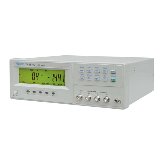
- Page 1 OPERATION MANUAL TH2810D LCR Meter TONGHUI (CHANGZHOU) Electronic Co., Ltd. Second Edition www.tonghui.com.cn...
-
Page 2: Table Of Contents
CHAPTER 1 PREPARATION ........................1-8 1.1 U NPACKING AND NSPECTION ......................... 1-8 1.2 P OWER EQUIREMENTS ......................... 1-8 1.3 L OLTAGE AND ELECTION ....................1-8 1.4 O PERATION NVIRONMENT ........................1-9 1.5 U IXTURE ..........................1-9 1.6 W UP AND ONTINUOUS ORKING .................. - Page 3 EFINITION ..........................4-31 4.2.2 E LECTRICAL HARACTERISTICS ....................... 4-36 CHAPTER 5 RS232C SERIAL INTERFACE ..................5-38 5.1 I NTRODUCTION ............................5-38 5.2 TH2810D’ ERIAL NTERFACE ......................5-38 5.3 C OMMUNICATION WITH OMPUTER ....................5-39 5.4 S ERIAL PORT PARAMETER ........................5-39 5.5 S...
- Page 4 7.2 N OTATION ONVENTIONS AND EFINITIONS ...................47 7.3 C OMMAND TRUCTURE ..........................47 7.4 C OMMAND BBREVIATIONS ........................49 7.5 H EADER AND ARAMETERS ........................49 7.6 C ..........................50 OMMAND ESCRIPTION 7.6.1 SPEED C OMMAND ..........................50 7.6.2 DISP OMMAND ..........................50 7.6.3 FREQ UENCY OMMAND ........................51...
- Page 5 Manual Print History The manual print history shown below lists all the printing dates and editions. The printing date changes when a new edition is released. The latest editions can be downloaded from our website. March 2006 ………………………………… First Edition December 2007 ……………………………...
- Page 6 Warranty This Tonghui instrument product is warranted against defects in material and workmanship for a period of two years from the date of shipment. Other items such as test fixtures, test cables are warranted for 90 days from the date of shipment. During the warranty period, we will, at our option, either repair or replace products which prove to be defective.
- Page 7 Safety Precautions The following safety precautions must be observed to avoid injury and prevent damage to this product or any products connected to it. To avoid potential hazards, read the operating information carefully before using the product and use this product only as specified.
-
Page 8: Chapter 1 Preparation
If the shipping container or cushioning material is damaged, it should be kept until the contents of the shipment have been checked for completeness and the TH2810D has been checked mechanically and electrically. The contents of the shipment should be as listed in the packing list. -
Page 9: Operation Environment
(1) The Please do not operate the instrument in places where there is dusty, vibrant, under direct sunlight, or where there is corrosive air. (2) In order to maintain good measurement accuracy, the TH2810D must be operated under the following environment conditions: Temperature: 0°C ~ 40°C... -
Page 10: Warm-Up And Continuous Working Time
For DUT which has shield, please connect the shield to the ground terminal “┴” of the instrument. Warm-up and Continuous Working Time Warm up the instrument for a minimum time of 15 minutes in order to ensure measuring precision. Continuous working time should be less than 16 hours. Other features (1) Power consumption:... -
Page 11: Chapter 2 Panel Description
Chapter 2 Panel Description This chapter provides information including a tour of the front and rear panel and display area definition, which will help you to quickly learn how to operate the TH2810D. A Tour of the Front Panel Figure 2-1 shows the brief description of each key on the TH2810D’s front panel. - Page 12 c) LEVEL key: The primary function is the setup key of test voltage level. Under input status (“ENTRY” is lighted), it is the exit key [ESC]. The secondary function is the sorting limits setup key LIMITS. d) DISP key: The primary function is the setup key of main parameter display mode. Under input status (“ENTRY”...
-
Page 13: A Tour Of The Rear Panel
This is the frame terminal which is tied to the instrument’s chassis and which can be used for measurements that require guarding. A Tour of the Rear Panel Figure 2-2 shows a brief description of the TH2810D’s rear panel. CAUTION: A C H A R G E D C A P A C I T O R 1.DO NOT CONNECT A DC CURRENT/VOLTAGE SOURCE OR... - Page 14 HAN NDLER inte erface. splay Area a Definition Figure 2-3 3 shows th he display a area defini tion of the TH2810D LCD scree Figure 2-3 D Display Are ea Definition (1) The S Secondary y Function Indicatio “SHIFT T”...
- Page 15 “P3” is on: Bin 3. “AUX” is on: Auxiliary bin. (6) Unit of The primary Parameter Indication Indicate the current unit of measurement result of the primary parameter. Unit of inductance:μH, mH, H. Unit of capacitance:pF, nF, μF, mF. Unit of resistance/impedance:Ω, kΩ, MΩ. (7) Signal Source Output Impedance Indication “30Ω”...
- Page 16 Display the current measurement result of the primary parameter. (15) Measurement Speed Indication “FAST” is on: Fast measurement speed “MED” is on: Medium measurement speed “SLOW” is on: Slow measurement speed (16) The Secondary Parameter Indication Indicate the current measuring secondary parameter user selected. (17) Measurement Mode Indication “CONT”...
-
Page 17: Chapter 3 Operation
⑩ Secondary parameter measurement result display The Primary Function Operation 3.2.1 Measurement Function TH2810D measures two components of the complex impedance parameters at the same time in a measurement cycle. The primary and secondary measurement parameters are listed as follows. -
Page 18: Test Frequency
5. Keep on pressing PARA key, until the measurement function required is indicated. 3.2.2 Test Frequency TH2810D provides 4 typical frequency points: 100 Hz, 120 Hz, 1 kHz and 10 kHz. The current test frequency is displayed on the bottom area of LCD. -
Page 19: Test Signal Level
5. Keep on pressing LEVEL key, until the test signal level required is indicated on the bottom of LCD. 3.2.4 Primary Parameter Display Mode TH2810D provides three kinds of display modes for the primary parameter: DIR: Direct reading display mode : Absolute deviation display mode ⊿... -
Page 20: Measurement Speed
5. Keep on pressing DISP key, until the display mode required is indicated on the top of 3.2.5 Measurement Speed TH2810D provides 3 kinds of measurement speeds: FAST, MED and SLOW. Generally, a slow measurement speed will result in more stable and accurate measurement results. - Page 21 When the measurement range is set manually, the optimum measurement range should be selected by matching the DUT’s impedance to the effective measuring range shown in Table 3-1 and Table 3-2. When the measurement range is set to AUTO, the optimum measurement range is automatically selected according to the impedance of each DUT, regardless of what kind of component is measured, a capacitor, a resistor or an inductor.
- Page 22 Notice: In measurement range “HOLD” mode, if the measured impedance is out of the effective measuring range or display range of the current fixed range, “-----” will be displayed instead of the measurement results. An example of how to calculate the optimum measurement range. For a capacitor DUT, if C=210nF, D=0.0010, and measurement frequency f=1 kHz.
-
Page 23: The Secondary Function Operation
The Secondary Function Operation 3.3.1 Correction TH2810D’s OPEN correction capability cancels errors due to the stray admittance (G, B) in parallel with the device under. TH2810D’s SHORT correction capability corrects for the residual impedance (R, X) in serial with the device under test. - Page 24 13. The SHORT correction is performed at all frequency points and ranges. The current frequency and range being corrected are displayed on the bottom of LCD. 14. TH2810D judges the results of correction measurement automatically. If the current correction result is not correct, TH2810D will interrupt the current correction operation and return to the measurement status.
-
Page 25: Comparator Function
L, C, R, and Z can be inputted. Do not enter a value which is lower than the LOW limit in the tolerance sorting mode. If you do, the TH2810D will never sort a device into the Bin you specified. The key functions under limits input (“ENTRY” is lighted) status are described in table 3-3. - Page 26 Table 3-3 The key functions under limits input status Main Menu Data Input Status Select the previous limit Move to the left digit Select the next limit Move to the right digit Select the main parameter of Add 1 to the current digit/Move ...
-
Page 27: Signal Source Output Impedance
3.3.3 Signal Source Output Impedance TH2810D provides two different signal output impedance 30Ω and 100Ω. The measurement current through the DUT will be different with different signal output impedance under the test same signal voltage level. The current sensitive components, for example the inductors with cores, will get different measurement results under different signal source output impedance. -
Page 28: Beep Function
4. Repeat step 2 and 3, signal source output impedance will be switched between 30Ω and 100Ω. 3.3.4 Beep Function TH2810D provides the beep alarm function under the specified sorting result. The beep statuses are listed as follows: OFF: Beep alarm function is OFF. -
Page 29: Equivalent Circuit
LCD. 3.3.6 Equivalent Circuit 3.3.6.1 Series and Parallel Circuit Setup TH2810D provides the series and parallel equivalent circuit modes for measuring the L, C, and R. Perform the following steps to set the equivalent circuit mode 1. -
Page 30: Rs232 Serial Interface
3.3.7 RS232 Serial Interface TH2810D provides the RS232 serial interface to communicate with a PC. All key functions on the panel can be accomplished through the interface, and the measuring settings and results can also be inquired and collected. -
Page 31: Chapter 4 Handler Interface
The comparison output signals include /P1, /P2, /P3, /AUX and /NG. Using these signals, the TH2810D can easily be combined with a component handler and a system controller to fully automate component testing, sorting, and quality control data processing to increase production efficiency. - Page 32 Notice: The “/” (black slash) in front of the signal name means that the signal is asserted when LOW. Primary parameter High parameter High Secondary Figure 4-1 /P1, /P2, /P3, /AUX, /NG signal’s area example Contact assignment is described in Table 4-2, Pin assignment for handler interface connector is shown in Figure 4-2 and the timing diagram for handler interface is shown in Figure 4-3.
- Page 33 EXTV. /AUX Build-in pull-up resistance is 4.7kΩ. External Trigger: 12,13 /TRIG TH2810D is triggered on the rising edge of a pulse applied to this pin. 14,15 No Connection Internal +5V voltage supply.(max. 0.3A) Generally, internal power supply is not recommended 16,17,18 to be used.
- Page 34 Figure 4-2 Pin Assignment for Handler Interface Connector 4-34...
- Page 35 a measurement a measurement Delay Measurement Comparison Display Time Time Time Time Time Minimum Value Maximum Value T1 Trigger Pulse Width 1 us T2 Measurement Start Delay Time 200us display + 200us T3 Trigger Wait Time After /EOM 0 us Output 1.
- Page 36 The /TRIG signal (pin 12 and 13) is connected to the cathode of the LED in an opto-coupler. The TH2810D is triggered on the rising edge of the /TRIG pulse. The anode ot the LED can be powered from the internal +5V supply, or by an external voltage source (EXTV).
- Page 37 Figu ure 4-4 Sim mplified D Diagram of f output an nd contro l signals se the inte ernal pow wer: ins 1 and 2 2 of the jum mper J205 should be e connected ins 1 and 2 2 of the jum mper J204 should be e connected...
- Page 38 RS S232C stan ndard, the signals ar re listed as shown in T Table 5-2. ble 5-2 T TH2810D S Serial Sign nals Pin Nu umber of 9 Function Code Pin C Connector ransmit Da...
-
Page 39: Communication Witha Computer
TH2810D executes the command after the end character NL is received. 3) The character received by TH2810D will be sent back to the controller again. The controller will not send the next character until the last return character is received correctively from TH2810D. - Page 40 B. Check if the RS232 function is turned on and TALK ONLY function is turned off. C. When TH2810D is executing a bus command, TH2810D will not accept any character through the serial interface at the same time and the character sent by controller will be ignored.
-
Page 41: Chapter 6 The Specifications
Chapter 6 The Specifications The complete TH2810D specifications are listed below. These specifications are the performance standards. When shipped from the factory, the TH2810D meets the specifications listed in this section. Measurement Functions 1. Primary measurement parameters Inductance C: Capacitance... -
Page 42: Measurement Range
LC oscillator, then the parallel circuit mode should be selected. Measurement Range When TH2810D is operated under 100Ω signal source output resistance, 5 ranges are available: 30Ω, 100Ω, 1kΩ, 10kΩ and100kΩ. When TH2810D is operated under 30Ω signal source output resistance, 6 ranges are available: 10Ω, 30Ω, 100Ω, 1 kΩ, 10 kΩ... -
Page 43: Trigger Mode
Trigger Mode TH2810D provides 4 kinds of trigger modes for selection. They are Internal, External, Bus and Manual. Internal: When the measurement mode is set to “CONT”, TH2810D is triggered automatically. TH2810D performs measurements continuously. External: When the measurement mode is set to “TRIG” and the handler interface is enabled, TH2810D performs a single measurement every time a low-to-high transition TTL level signal is applied to the handler interface on the rear panel. -
Page 44: Maximum And Minimum Values Used For Accuracy Calculation
6.7.3 Measurement Voltage Level Factor kv 1.0Vrms: kv=0; 0.3Vrms: kv=1; 0.1Vrms: kv=4. 6.7.4 Measurement Frequency Factor kf 100Hz: kf=0; 120Hz: kf=0; 1kHz: kf=0; 10kHz: kf=0.5; Measurement Frequency TH2810D provides 4 kinds of test frequencies: 100Hz, 120Hz, 1kHz and 10kHz. Accuracy: ±0.02%... -
Page 45: Test Signal Level
6.13 Comparator Function TH2810D’s built-in comparator can short devices into a maximum of 4 bins (P1, P2, P3 and NG) using a maximum of three pairs of primary limits and one pair of secondary parameter limits. Also, a device whose primary parameter is within limits, but whose secondary parameter measurement result is not within limits can be sorted into an AUXiliary bin. -
Page 46: Ranging Mode
ASCII codes over the bus. 6.17 HANDLER interface TH2810D can receive the Trigger signal and output the comparison results through the HANDLER interface. Synchronous signal /IDX and /EOM can be outputted. The output signals are logical low active and opto-isolated. -
Page 47: Chapter 7 Command Reference
For example, Carriage Return (13 decimal) or Space (32 decimal). Command Structure The TH2810D commands are divided into two types: Common commands and SCPI commands. The common commands are defined in IEEE std, and these commands are common for all devices. The SCPI commands are tree structured three levels deep. The highest level commands are called the subsystem commands in this manual. - Page 48 The basic rules of the command tree are as follows. Letter case (upper and lower) is ignored. For example, LIMIT:NOMINAL <value> = limit:nominal <value> = LiMiT:NoMiNaL <value> Spaces (︺ used to indicate a space) must not be placed before and/or after the colon(:).
-
Page 49: Command Abbreviations
Source RESistor abbreviates to SRES. The long form is SRESISTOR. Header and Parameters The TH2810D control command consists of a command header and parameters. Headers can be of the long form or the short form. The long form allows easier understanding of the program code and the short form allows more efficient use of the computer. -
Page 50: Command Description
Examples for NR3: 12.3E+5 123.4E-56 Command Description. 7.6.1 SPEED Command The SPEED command sets the measurement speed of TH2810D. The SPEED? query returns the current measurement speed setting. Command Syntax: FAST SPEED MEDium SLOW Where, FAST fast measurement speed, approx. 10 meas/sec. -
Page 51: Frequency Command
Query Syntax: DISPlay? Query Response: DIRECT PERCENT , <NL> ABSOLUTE 7.6.3 FREQuency Command The FREQuency command sets the signal source frequency. The FREQuency? query returns the current test frequency. Command Syntax: FREQuency Where, Set measurement frequency to 100 Hz. Set measurement frequency to 120 Hz. Set measurement frequency to 1 kHz. -
Page 52: Level Command
Where, Set measurement parameter combination to C-D. Set measurement parameter combination to R-Q. Set measurement parameter combination to Z-Q. Set measurement parameter combination to L-Q. Query Syntax: PARAmeter? Query Response: , <NL> 7.6.5 LEVel Command The LEVel command sets the oscillator’s output voltage level. The LEVel? query returns the current oscillator voltage level. -
Page 53: Sresistor Command
7.6.6 SRESistor Command The SRESistor command sets the signal source output resistor. The SRESistor? query returns the current setting of the signal source output resistor. Command Syntax: SRESistor Where, Set the signal source output resistor to 30Ω. Set the signal source output resistor to 100Ω. Query Syntax: SRESistor? Query Response:... -
Page 54: Correction Command
7.6.8 CORRection Command The CORRection command executes the OPEN or SHORt correction for all frequencies over the specified voltage level and signal source output resistor. Command Syntax: OPEN CORRection OPEN_ALL SHORt SHORt_ALL Where, OPEN Execute the OPEN correction for all frequencies over the specified voltage level and signal source output resistor. -
Page 55: Equivalent Command
7.6.10 EQUivalent Command The EQUivalent command set the equivalent circuit mode for measurement. The EQUivalent? query responds the current equivalent circuit used for measurement. Command Syntax: SERial EQUivalent PARallel Where, SERial Set the equivalent circuit mode to serial circuit mode. PARallel Set the equivalent circuit mode to parallel circuit mode. -
Page 56: Alarm Command
Where, AUTO Set the ranging mode to AUTO. HOLD Set the ranging mode to HOLD. 0 to 5 Set the current measurement range. Query Syntax: RANGe? Query Response: AUTO-<n> , <NL> HOLD-<n> 7.6.12 ALARm Command The ALARm command sets which Bin is to be alarmed. ALARm? query returns the current BIN to be alarmed. -
Page 57: Limit Subsystem
7.6.13 LIMit Subsystem LIMit:NOMinal The LIMit:NOMinal command sets the nominal value for the tolerance mode of the comparator function. The LIMit:NOMinal? query returns the current settings of the nominal value for the tolerance mode. Command Syntax: LIMit:NOMinal_C <value> LIMit:NOMinal_L <value> LIMit NOMinal_Z <value>... -
Page 58: Fetch? Query
LIMit:SECondary? query returns the current settings of the secondary parameter low/high limit values. Command Syntax: LIMit:SECondary <low limit>,<high limit> Where, <low limit> NR1, NR2, NR3 format low limit value <high limit> NR1, NR2, NR3 format high limit value Query Syntax: LIMit:SECondary? Query Response: <low limit >,<high limit>...
Need help?
Do you have a question about the TH2810D and is the answer not in the manual?
Questions and answers