Table of Contents
Advertisement
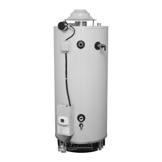
GAS-FIRED COMMERCIAL WATER HEATER
INSTALLATION/OPERATION MANUAL
PLACE THESE INSTRUCTIONS ADJACENT TO WATER HEATER AND NOTIFY OWNER TO KEEP FOR FUTURE REFERENCE
-
Do not store or use gasoline or other
flammable vapors and liquids in the
vicinity of this or any other appliance.
- WHAT TO DO IF YOU SMELL GAS
•
•
•
•
-
For your family' s comfort, safety and
convenience, it is recommended this
w ater heater be installed and serviced by
a plumbing professional.
WITH TROUBLESHOOTING GUIDE
WARNING: If the information in
these instructions is not followed
exactly, a fire or explosion may
result causing property damage,
personal injury or death.
Do not try to light any appliance.
Do not touch any electrical sw itch; do
not use any phone in your building.
Immediately call your gas supplier
from a neighbor' s phone. Follow the
gas supplier' s instructions.
If you cannot reach your gas supplier,
call the fire department.
238-47675-00F 8/18
Advertisement
Table of Contents


Need help?
Do you have a question about the Magnum D75T125E3N and is the answer not in the manual?
Questions and answers