Page 1
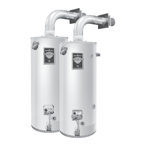
Flammable Vapor Ignition Resistant Water Heaters Direct Vent Water Heaters SERVICE MANUAL Troubleshooting Guide and Instructions for Service (To be performed ONLY by qualified service providers) Models Covered by This Manual: RG2DV40S*(N,X) RG2DV50S*(N,X) RG2DV50H*(N,X) LG2DV50H50*(N,X) (*) Denotes Warranty Years Manual 238-51636-00C REV 08/19 Save this manual for future reference...
The Bradford White DV Series Direct Vent Water Heaters Table of Contents Page SVC Procedure Introduction ................4 Tools Required for Service ............5 Troubleshooting Charts .............6 Inner Door Removal and Replacement ........12 Thermocouple/Thermopile Testing ...........15 Igniter, Electrode Testing, and Replacement ......18 Gas Control Testing and Replacement ........19...
Page 3
DV Series WARNING: If the information in these instructions is not followed exactly, a fire or explosion may result causing property damage, DANGER personal injury, or death. DO NOT store or use gasoline or FOR YOUR SAFETY other flammable, combustible, or...
DV Series Introduction The new Bradford White DV water heaters are designed to provide reliable performance with enhanced standard features. Design features include reliable standing pilot ignition system, enhanced diagnostics, simplified servicing, and certified FVIR technology. The DV water heaters use a combustion system where combustion air is drawn from the outside of the building.
It is intended for this manual to be used by qualified service personnel for the primary purpose of troubleshooting and repair of the Bradford White DV Series water heaters. The Honeywell Icon Gas Control will display status codes in the event of abnormal operation.
Page 6
DV Series Troubleshooting Gas Control V1 Observe green LED indicator on electronic gas control. Status flash codes are displayed with a three second pause before repeating. Check and repair the system as noted in the troubleshooting table below. LED Status...
Page 7
DV Series Troubleshooting Gas Control V1 Observe green LED indicator on electronic gas control. Status flash codes are displayed with a three second pause before repeating. Check and repair the system as noted in the troubleshooting table below. LED Status...
Page 8
DV Series Troubleshooting Gas Control V2 Observe colored LED indicator on electronic gas control. Status flash codes are displayed with a three second pause before repeating. Check and repair the system as noted in the troubleshooting table below. LED Status...
Page 9
DV Series Troubleshooting Gas Control White Rodgers Mechanical Symptom Probable Cause Corrective Action Service Procedure 1. No incoming gas or too low 1. Turn on gas supply and/or check gas pressure. line pressure. 2. Gas control knob set to 1. See Service wrong position.
Page 10
DV Series Troubleshooting Gas Control White Rodgers Mechanical Symptom Probable Cause Corrective Action Service Procedure 1. Verify adequate combustion air is available to the unit. Check and clear jacket slot openings of 1. Insufficient combustion air any dirt, dust, restrictions or Pilot goes out supply.
Page 11
DV Series Troubleshooting Gas Control White Rodgers Electronic Observe green LED indicator on gas control. Status flash codes are displayed with a three second pause before repeating. Check and repair the system as noted in the troubleshooting table below. LED Status...
Service Procedure I DV Series Inner Door Removal and Replacement Inner Door Removal Procedure Step 1. Rotate the gas control knob to the “OFF” position. Step 2. Remove the outer jacket burner access door. Step 3. Remove the wire clip from the feedline (if present).
Page 13
Service Procedure I DV Series Inner Door Removal and Replacement Inner Door Gasket Replacement Procedure (cont.) Step 2. Use RTV sealant (recommended bead size 1/8”) to secure the inner door gasket to the inner door sections (right & left). Refer to the illustrations on the next page for proper application.
Page 14
Service Procedure I DV Series Inner Door Removal and Replacement Installation of Inner Door with Gasket (cont.) Step 5. Align right side inner door to combustion chamber and verify the fastener holes of the combustion chamber are aligned with right side inner door slotted opening.
Service Procedure II DV Series Thermocouple/Thermopile Testing and Replacement Closed Circuit Thermocouple Testing (White Rodgers Mechanical) Step 1. Closed circuit testing is the preferred method for testing the thermocouple. Following the lighting instruction label on the heater, proceed to light the pilot and allow to operate for three minutes.
Page 16
Service Procedure II DV Series Thermocouple/Thermopile Testing and Replacement Thermocouple Replacement (White Rodgers Mechanical) Step 1. Turn off gas supply to the water heater. Rotate the knob of the combination thermostat/gas valve to “OFF” position. Step 2. Remove the outer jacket door.
Page 17
Service Procedure II DV Series Thermocouple/Service Testing and Replacement Closed Circuit Thermopile Testing (White Rodgers Electronic and Honeywell) Closed circuit thermopile testing is the preferred method for testing the thermopile. Step 1. Following the lighting instruction label on the heater, proceed to light the pilot and allow to operate for three minutes.
Service Procedure III DV Series Igniter, Electrode Testing, and Replacement Igniter, Electrode Testing and Replacement Step 1. Remove the outer jacket door. Step 2. Repeatedly depress the igniter button while viewing the pilot through the flame viewing window. If a spark is present, the circuit is O.K.. If there is no spark, proceed to Step 3.
Service Procedure IV DV Series Gas Control Testing and Replacement Line Pressure The gas control is designed for a maximum line pressure of 14.0” W.C. and a minimum line pressure of the water heater’s rated manifold pressure plus 1.0” W.C. (check rating plate). Line pressure must be checked with the main burner on AND off to assure proper readings.
Page 20
Service Procedure IV DV Series Gas Control Testing and Replacement Gas Valve Testing and Replacement (White Rodgers Mechanical) The gas valve on the White Rodgers Mechanical is a non-repairable device. If troubleshooting has determined a problem with the gas valve, it must be replaced.
Page 21
Service Procedure IV DV Series Gas Control Testing and Replacement For White Rodgers Control, Combination Thermostat/Gas Valve Replacement depress knob slightly and rotate clockwise to the “OFF” position (White Rodgers Mechanical) Step 1. Rotate the knob of the gas valve to the “OFF” position.
Page 22
Service Procedure IV DV Series Gas Control Testing and Replacement Combination Thermostat/Gas Valve Replacement (cont.) (White Rodgers Mechanical) Step 8. Installation of gas valve: a. Install new gas valve using a control body wrench or a length of 1/2" NPT pipe threaded into inlet of control.
Page 23
Service Procedure IV DV Series Gas Control Testing and Replacement Combination Thermostat/Gas Valve Replacement (cont.) c. Position thermocouple, pilot tube and piezo wire against left side inner door flange gasket. DO NOT ROUTE THROUGH RADIUSED CHANNEL WITH FEEDLINE. Be sure that thermocouple and pilot tube are not in position to interfere with outer jacket burner access door when reinstalled.
Page 24
Service Procedure IV DV Series Gas Control Testing and Replacement (Honeywell ONLY) NOTE: The following procedure applies to the Honeywell gas controls ONLY. Honeywell Cover Removal CAUTION Step 1. Rotate the knob of the gas control to the “OFF” Use caution to not bend or position.
Page 25
Service Procedure IV DV Series Gas Control Testing and Replacement (Honeywell ONLY) Honeywell Cover Removal (cont.) Step 6. Depress both tabs on the top of the gas control cover (Honeywell V1 only) and pull straight out to remove. Valve body pins Step 7.
Page 26
Service Procedure IV DV Series Gas Control Testing and Replacement (Honeywell ONLY) Honeywell Cover Removal (cont.) Temperature sensor wire routing clip Disconnect temperature sensor Step 8. Remove the piezo igniter from the control cover by releasing the lock tab on the...
Page 27
Service Procedure IV DV Series Gas Control Testing and Replacement (Honeywell ONLY) Honeywell Valve Body Removal and Temperature Sensor Removal Step 1. Disconnect the burner and pilot tubes per Service Procedure II. CAUTION Step 2. Remove the valve body by removing the screw located at the lower Use caution to not left corner.
Page 28
Service Procedure IV DV Series Gas Control Testing and Replacement (Honeywell ONLY) Honeywell Valve Body Removal and Temperature Sensor Removal (cont.) Step 4. Remove the temperature sensor from the insertion stick by pulling it apart as illustrated below. Temperature sensor...
Page 29
Service Procedure IV DV Series Gas Control Testing and Replacement (Honeywell ONLY) Temperature Sensor Testing (Honeywell) Step 1. If control has gone into lockout due to excessive CAUTION tank temperature (four flashes, three second DO NOT use standard pause), reset control by rotating gas control knob multimeter probes for this test.
Page 30
Service Procedure IV DV Series Gas Control Testing and Replacement Determine Water Temperature Inside Tank NOTE: It is important to understand once the resistance for the temperature sensor is determined from the previous page, water flow through the water heater should not occur. Prior to drawing water from drain valve, turn off the cold-water supply to the water heater.
Page 31
Service Procedure IV DV Series Gas Control Testing and Replacement Gas Control Replacement (White Rodgers Electronic and Honeywell) Step 1. Rotate the gas control knob to the “OFF” position. Step 2. Turn off gas supply to the water heater. Step 3. Disconnect the gas supply line from the gas control.
Page 32
Service Procedure IV DV Series Gas Control Testing and Replacement Gas Control Replacement (cont.) b. Reattach the main burner feedline, pilot tube, igniter wire, inner door wire (red), and thermopile wire (white) to the gas control. Attach the inner door wire (red) to the positive (+) terminal and the thermopile wire (white) to the negative (-) terminal.
Page 33
Service Procedure IV DV Series Gas Control Testing and Replacement Gas Control Replacement (cont.) d. Firmly place right side inner door flange against the left side inner door flange and secure with two (2) 1/4” hex drive screws from Step 6c. DO NOT OVER TIGHTEN SCREWS.
Service Procedure V DV Series Burner Operation Inspection, Cleaning, and Replacement Burner Inspection At periodic intervals (every 6 months) a visual inspection should be made of the pilot and main burner for proper operation and to assure no debris is accumulating.
Page 35
Service Procedure V DV Series Burner Operation Inspection, Cleaning, and Replacement Burner Cleaning Step 1. Follow the steps in “Burner Removal” on page 33. Step 2. Thoroughly inspect the burner surface area and the burner port area and remove any loose debris.
Service Procedure VI DV Series Pilot Testing, Cleaning, and Replacement Pilot Inspection, Testing, and Replacement Honeywell Pilot Step 1. Remove burner following the steps listed in “Burner Removal” on page 33. Step 2. Remove the pilot assembly from the feedline (1/4”...
Service Procedure VII DV Series Resettable Thermal Switch Testing and Replacement Resettable Thermal Switch Continuity Testing Step 1. Remove the outer jacket door. Step 2. Disconnect the wire leads from the resettable thermal switch. Step 3. Using a multimeter capable of measuring continuity...
Page 38
Service Procedure VII DV Series Resettable Thermal Switch Testing and Replacement Resettable Thermal Switch Replacement Step 1. Rotate the knob of combination thermostat/gas valve to the “OFF” position. Step 2. Remove the outer jacket door. Step 3. Disconnect the wire leads from the resettable thermal switch.
Service Procedure VIII DV Series Diptube Inspection and Replacement Diptube Inspection and Replacement WARNING Water heater components and stored water may be HOT when performing the following steps in this procedure. Take necessary precaution to prevent personal injury. Step 1. Position the gas control knob to the “OFF” position.
Service Procedure IX DV Series Anode Inspection and Replacement Anode Inspection and Replacement WARNING Water heater components and stored water may be HOT when performing the following steps in this procedure. Take necessary precaution to prevent personal injury. Step 1.
DV Series Glossary of Terms Glossary of Terms British thermal units Gallons per minute Hertz Kilowatt hour Light emitting diode National pipe thread Ohms Ohms of resistance Pounds per square inch Revolutions per minute Energy cut out Volts alternating current Inches of water column “W.C.
DV Series Parts Diagram Venting Package Complete 11. Inlet Diptube 21. Feedline Clip Venting Protection Screen 12. T&P Valve 22. Right Side Inner Door Plenum 13. 3/4 NPT plug (“H” Models only) 23. Left Side Inner Door Plenum Gasket 14. Air Intake Boot 24.
Need help?
Do you have a question about the DV Series and is the answer not in the manual?
Questions and answers