
Subscribe to Our Youtube Channel
Related Manuals for ARB AIRLOCKER RD153


Summary of Contents for ARB AIRLOCKER RD153
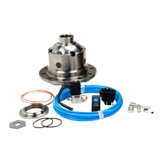
- Page 1 RD153 TOYOTA 8.9”, C-CLIP, 50MM CARRIER BEARING AIR OPERATED LOCKING DIFFERENTIAL INSTALLATION GUIDE...
- Page 2 No liability is assumed for damages resulting in the use of the information contained herein. ARB AIR LOCKER Locking Differentials and AIR LOCKER are trademarks of ARB Corporation Limited. Other product names used herein are for identification purposes only and may be trademarks of their respective owners.
-
Page 3: Table Of Contents
Table of Contents: 1 Introduction 1.1 Pre-Installation Preparation 1.2 Tool-Kit Recommendations 2 Removing the Existing Differential 2.1 Vehicle Support 2.2 Differential Fluid Drain 2.3 Removing the Axles 2.4 Marking the Bearing Caps 2.5 Checking the Current Backlash Amount 2.6 Removing the Differential Carrier 3 Installing the Air Locker 3.1 Mounting the Ring Gear 3.2 Installing the Carrier Bearings... -
Page 5: Introduction
Although your ARB Air Locker comes complete with all the step by step instructions you will need to supplement your vehicle manufacturer’s service manual and install your new differential, ARB recommends that you have your Air Locker installed by a trained professional. -
Page 6: Tool-Kit Recommendations
A dial indicator or other suitable measuring tool for checking ring & pinion backlash. An adjuster-nut wrench. (e.g., ARB Adjuster Nut Pliers #0770002.) A razor knife suitable for cutting nylon tubing. A torque wrench. (See your vehicle service manual for the required torque range.) -
Page 7: Removing The Existing Differential
Any misalignment of the axle tubes may result in excessive wear and/or failure of your differential and axle shafts. ARB strongly recommends that you have your axle assembly inspected for concentricity and straightness before installing your Air Locker. - Page 8 2 Removing the Existing Differential Gently tap axles outward and remove them from the differential center. NOTE : Rubber oil seals can be easily damaged. Support the weight of the axle when extracting it across the edges of the seals. ...
-
Page 9: Marking The Bearing Caps
2 Removing the Existing Differential Marking the Bearing Caps Using a small pointed center punch, gently mark the bearing caps in a way that will enable you to know which cap is ‘LEFT’ and which cap is ‘RIGHT’, which way is ‘UP’ and which way is ‘DOWN’. (Fig.1.) ... -
Page 10: Checking The Current Backlash Amount
2 Removing the Existing Differential Checking the Current Backlash Amount IMPORTANT: This step is a precautionary measure recommended by ARB due to the fact that some after market ring and pinion sets have been manufactured to run with different backlash settings than those specified by your vehicle manufacturer. -
Page 11: Removing The Differential Carrier
Remove the adjuster nuts. Carefully remove the differential carrier from the third member. Remove the tapered roller bearings from the differential carrier with a bearing puller (ARB #0770001). (Fig.3.) HINT : Check the condition of the bearing for wear and replace if necessary. -
Page 12: Installing The Air Locker
3 Installing the Air Locker Mounting the Ring Gear Remove the bolts that hold the ring gear in place. Using a plastic or copper hammer, tap in a circle around the ring gear to separate it from the differential carrier. ... -
Page 13: Installing The Carrier Bearings
50mm bearings: Timken # 32010X-32010X ARB # 160116 If your OE carrier bearings have an ID of 50mm, replace them with new bearings of the same type. Apply a thin film of high pressure grease to the bearing journals of the Air Locker, then press the bearing cones onto the bearing journals as shown in Figure 5. -
Page 14: Drilling And Tapping The Bulkhead Port
3 Installing the Air Locker Figure 5. Drilling and Tapping the Bulkhead Port An air line port must be drilled and tapped through the differential housing to mount the bulkhead fitting into. Mark a spot on the right hand side (opposite the ring gear) toward the top of the differential housing that is in an area well clear of the differential, the ring gear, and any other obstructions that could snag the seal housing tube. -
Page 15: Final Air Locker Assembly
Insert the original adjuster nut onto the opposite side of the differential and tighten with the appropriate adjuster nut wrench (ARB #0770002). NOTE : You should now feel some backlash between the ring and pinion gears. If not, there might be a clearance problem which is binding the carrier. -
Page 16: Checking The Backlash
3 Installing the Air Locker Checking the Backlash Set a depth indicator on one of the ring gear teeth. (Fig.7.) While supporting the pinion gear by holding the drive shaft flange, rotate the differential in both directions while observing the maximum variation in depth from the indicator (i.e., the highest value minus the lowest value). -
Page 17: Installing The Seal Housing
3 Installing the Air Locker Installing the Seal Housing Make sure the grooves and airway of the seal housing are clean and free from any contaminants (e.g. water, dirt, metal filings, etc.). Inspect the seal housing O-rings (supplied) for dirt, damage or other conditions which might cause leaks. -
Page 18: Setting Up The Bulkhead Fitting
3 Installing the Air Locker Install the spring clip by first hooking both ends of the clip into the small aligned cutouts of the seal housing and the adjuster nut, and then snapping the clip into the groove of the seal housing using a screwdriver. - Page 19 3 Installing the Air Locker IMPORTANT: The seal housing must still be able to freely float after the tube is connected to the bulkhead fitting. Therefore, it is critical to ensure that the tube is not under any tension. To avoid this always leave the tube long enough so that a hook shape can be formed between the seal housing and the bulkhead.
- Page 20 3 Installing the Air Locker Figure 10. NOTE : Make sure the seal housing tube is all of the way into the center compression nut while you are tightening NOTE : Firmly tighten the center compression nut so that a good seal is formed around the tube.
-
Page 21: Profiling The Seal Housing Tube
3 Installing the Air Locker Profiling the Seal Housing Tube With the seal housing tube now firmly secured into the bulkhead fitting, bend the tube so that it closely follows the profile of the differential. (Figs.11.,12. & 13.) Check that the contour of the tube will not interfere with the bearing caps, the Air Locker, the ring gear or the axle housing. - Page 22 3 Installing the Air Locker Figure 13. IMPORTANT: In order for the seal housing to float and self center on the bearing journal, the seal housing tube must not be pulling against the seal housing. To check this, rotate the drive flange back and forth while observing the seal housing movement.
-
Page 23: Bench Testing The Air Locker
NOTE : An accurate way to test for air leaks is to fit a shut-off valve to an air pressure gauge (Available as ARB part #0770005). Charge with shop air until 620 KPA [90 PSI] is reached, shut the valve off, disconnect the air hose, and watch to see if there is any drop in pressure. -
Page 24: Reinstalling The Differential & Axles
3 Installing the Air Locker Reinstalling Differential and Axles 3.10 Undo the retaining pins on either side of the access window, and remove the 2 corresponding cross shafts, spider block and thrust block from the Air Locker. Replace the paper gasket on the axle housing flange. ... - Page 25 3 Installing the Air Locker Select the two C-clips which are closest to the thickness you calculated above without going over, and replace the ones you measured with. NOTE : The objective here is only to attain a slip fit between the thrust block and the axles without any slop (too loose) or binding (too tight).
-
Page 26: Installing The Air System
4 Installing the Air System Mounting the Solenoid Connection to an ARB Air Compressor (Fig.15.) 4.1.1 Remove one of the 1/8” BSP plugs from its port in the compressor tank. Apply Teflon paste to the 1/8” BSP nipple on the solenoid and insert it into the port and tighten. - Page 27 For ease of installation, quality of air supply, and a high level of dependability from your Air Locker(s), ARB strongly recommends use of a genuine ARB Air Compressor, however, the Air Locker air system can be operated on any alternate air source that meets each of the following guidelines: ...
-
Page 28: Running & Securing The Air Line
4 Installing the Air System Running and Securing the Air Line The path taken by the air line from your air source (i.e., compressor) to your Air Locker is unique to your vehicle and the position of your air source. Plan ahead carefully when running the air line and always follow these guidelines: ... -
Page 29: Connection To The Bulkhead Fitting
4 Installing the Air System NOTE : To remove the air line from the push-in fitting; push the air line as far into the fitting as possible and hold, push inward on the flange, and then pull the air line free of the fitting. - Page 30 4 Installing the Air System Push the airline into the compression fitting body and screw the outer nut down onto it. Using a 12mm spanner, tighten the outer nut onto the compression fitting body. NOTE : Some force is required to crush the ferrule, however the outer compression nut will tighten against a stop.
-
Page 31: Mounting & Connecting The Electrical System
Switch(es) should not be mounted where they will be exposed to water (e.g., in the lower section of an inner door panel). ARB recommends that you apply the Air Locker Warning Sticker (ARB part # 210101) within close visual proximity of the switch location. -
Page 32: Wiring The Actuator System
Connection to an ARB AIR COMPRESSOR 5.2.1 When wiring the Air Locker actuator switch(es) and solenoid(s) to an ARB Air Compressor, all connections can easily be set up directly from the supplied wiring loom. (Fig.18.) NOTE : 180409 model loom shown for reference only. Refer to your ARB Air Compressor Installation Guide for details on configuring your installation. - Page 33 5 Mounting & Connecting the Electrical System SWITCH TERMINAL IDENTIFICATION Figure 19. Connection to an Alternate Air Source 5 .2.2 When connecting the actuation switch to an alternate air source, the switch(es) should be wired according to figures 20. and 21. depending on whether one or two Air Lockers will be installed in the vehicle.
- Page 34 5 Mounting & Connecting the Electrical System Dual Air Locker System 5.2.2.2 If two Air Lockers are to be installed in the system, ARB recommends that the switches and solenoids be wired according to figure 21. For safety reasons, this configuration allows SOLENOID 2 to be actuated only if SOLENOID 1 is already on.
-
Page 35: Testing & Final Assembly
6 Testing & Final Assembly Leak Testing With the vehicle parked and the engine off, turn the compressor on and wait until the air system is fully charged. NOTE : With the Air Locker(s) disengaged, the air source (i.e., compressor) should not have to recharge over time. -
Page 36: Filling The Differential
Rotate the same wheel. The wheels should again rotate in opposite directions. Filling the Differential NOTE : Consult the ARB Air Locker Operating & Service Manual for recommendations on differential lubricant specifications. Refill the differential until level with the filler hole. -
Page 37: Post-Installation Check List
6 Testing & Final Assembly Post-Installation Check List Now that the Air Locker installation has been completed, ARB recommends that you take the time to complete the following check list just to insure that you haven’t missed any of the vital steps. - Page 38 6 Testing & Final Assembly...
-
Page 39: Parts List
7 Parts List Toyota 8.9”,C-clip,50mm BRNG RD153 Exploded Assembly Diagram (See itemized parts list overleaf) Figure 22. Specifications 30 tooth, Ø33mm [1.31”] Axle Spline Ratio Supported 138.1mm [5.44”] Ring Gear ID 225mm [8.9”] Ring Gear OD 12 bolts on Ø156mm [6.14”] Ring Gear Bolts Ring Gear Torque 120Nm [89 ft-lb]... -
Page 40: Itemized Parts List
For replacement O-rings use only BS136 Viton For 80mm Bearing OD use Timken Bearing #32010X (ARB# 160116). Available only as complete 5 gear set # 728H181C. Available only as complete thrust washer kit #730H01. Order thrust block 110102SP as replacement for RD153 with a long cross shaft (SN 1606XXXX &...
Need help?
Do you have a question about the AIRLOCKER RD153 and is the answer not in the manual?
Questions and answers