Advertisement
Quick Links
SWITCH 4008GT
Quick Installation Guide
Address of the manufacturer:
SALZ Automation GmbH
Max-Planck-Str. 64
32107 Bad Salzu en, Germany
Email: support@salz-automation.com
Please scan for more information:
1. Overview
The SWITCH 4008GT Lite-Managed Industrial Ethernet Switch and includes 8-port
10/100/1000Mbps RJ45 downlink ports.
2. Package Checklist
• SWITCH 4008GT Switch x 1
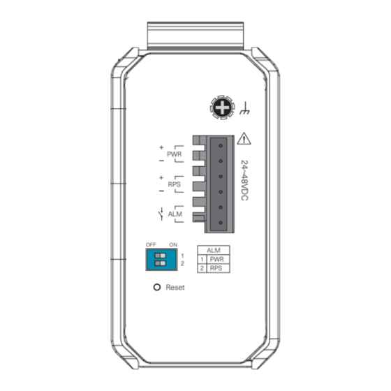
RPS
Panel view
PWR
Grounding
Screw
1
+
PWR
Power Input
3
+
Terminal Block
RPS
ALM
5
OFF
ON
DIP Switches
ALM
7
1
1 PWR
2
2
RPS
Reset
Top View
Grounding Screw
Front View
3. Mounting and Dismounting to DIN-Rail
Place the SWITCH
2008GT on the DIN
rail
from
above
using the slot, push
the front of the
switch toward the
mounting surface
until it snaps into
Click
place with a click
sound.
Mounting the Switch
Removing the Switch
!
ATTENTION: Ambient temperature should not exceed 70°C.
4. Grounding the switch SWITCH 4008GT
Step1:
Run
the
ground
connection
from
the grounding surface prior to connecting devices.
Step2:
Connect
the
ground
connection
from
to the grounding surface prior to connecting device.
-1-
!
ATTENTION: To be mounted on a well- grounded mounting surface such as a
metal panel.
5. Wiring requirements
WARNING:
!
Turn o the power before connecting modules or wires. The correct power supply
voltage is listed on the product label. Check the voltage of your power source to
make sure that you are using the correct voltage. DO NOT use a voltage greater than
what is speci ed on the product label. Calculate the maximum possible current in each
power wire and common wire. Observe all electrical codes dictating the maximum
current allowable for each wire size. If current exceeds the maximum rating, the wiring
can overheat causing serious damage to your equipment.
• Use separate paths to route wiring for power and devices. If power wiring and device
wiring paths must cross make sure the wires are perpendicular at the intersection
point.
NOTE: Do not run signal or communications wiring and power wiring through
the same wire conduit. To avoid interference, wires with di erent signal
characteristics should be routed separately.
•
You can use the type of signal transmitted through a wire to determine which wires
should be kept separate. The rule of thumb is that wiring that shares similar electrical
characteristics can be bundled together.
•
You should separate input wiring from output wiring.
•
We advise that you label the wiring to all devices in the system.
5.1 Wiring Power Input
5.1.1 SWITCH 4008GT with 6pin terminal block
ALM
1000
1000Mbps
(Green)
2
4
Terminal Block
6
8
LNK/ACT
LNK/
(Green)
ACT
To insert power wire and connect the 9 to 48 V DC at a maximum of 0.5 A DC power to
the power terminal block, Loosen the wire-clamp screws, Insert the negative/positive
DC wires into the ( - /+) terminals, respectively, and Tighten the wire-clamp screws.
ATTENTION: Please use a power supply from 9 to 48 V DC, the device power
!
shall be supplied by SELV circuit.
5.2 Wiring the relay contact (ALM)
Press the
switch from
top and pull
out the
lower edge
of the switch
and then
remove the
switch from
the DIN rail.
The SWITCH 4008GT has one set of relay alarm output. This relay contact uses two
contacts of the terminal block on the top panel.
The two contacts of the 6-pin terminal block connector are used to detect user-con g-
ured events. The two wires attached to the fault contacts form an open circuit when a
the
ground
screw
to
user-con gured event is triggered. If a user-con gured event does not occur, the fault
circuit remains closed.
the
terminal
block
Relay rating: 24V, 1A
Caution:
!
• Use copper conductors only
You can use "PWR"
• Wiring cable temperature should
for Primary Power
support at least 105˚C
input and "RPS" for
• Tighten the wire to a torque value
Redundant Power
20N
• The wire gauge for the terminal
Input.
block should range between 0.2 to
2.5 mm
2
Load
External
Power
-2-
5.3 Cabling RJ45
Connect one end of an Ethernet/RJ45 cable into Ethernet port of SWITCH 4008GT and
other end to attached networking device. Ports 1-8 of the switch support fast Ethernet
and Gbit Ethernet (10/100/1000Base-T RJ45 Ports) All the RJ45 ports on the SWITCH
4008GT support auto negotiation and auto MDI/MDI-X to eliminate the need for
crossover
cabling.
Note:
Category
5e
cable
or
6. DIP Switch Setting
ON: Primary power alarm reporting is enabled
1
OFF
ON
PWR
OFF: Primary power alarm reporting is disabled
1
ON: Redundant power alarm reporting is enabled
2
2
RPS
OFF: Redundant power alarm reporting is disabled
7. LED Indicators
Illuminated
Primary power on
PWR
(Green)
O
Primary power o or failure
Illuminated
Redundant power on
RPS
(Green)
O
Redundant power o or failure
Alarm triggered for abnormal power status
Illuminated
ALM
and anomalous features.
(Red)
O
Normal operation or DIP switch OFF
1000
Illuminated
Link speed at 1000Mbps
(Green)
(1~8
th
O
Link speed at 10/100Mbps
RJ45 port)
Illuminated
Port link-up
LNK/ACT
(Green)
Blinking
Activity (receiving or transmitting data)
(1~8
th
RJ45 port)
O
Port disconnected or link failed
8. Environmental limits
Operating Temperature
-40°C ... 75°C (-40°F ... 167°F)
Storage Temperature
-40°C ... 85°C (-40°F ... 185°F)
Ambient relative humidity
5 to 95% (non condensing)
ATTENTION:
!
This device complies with Part 15 of the FCC rules. Operation is subject to
the following conditions:
1. This device may not cause harmful interference.
2. This device must accept any interference received including interference
that may cause undesired operation.
ATTENTION:
!
If the equipment is used in a manner not speci ed by the SALZ
Automation GmbH, the protection provided by the equipment may be
impaired.
ATTENTION:
!
Please leave at least 5cm of space at the left and right of the unit for
ventilation.
9. Con guration
Connect through Web Browser:
• Connect your computer to one of the Ethernet ports.
• Use the default IP-address 192.168.0.254 to login to the switch.
Default Username
SALZ
Default Password
admin
NOTE: For more details on con guration please refer user manual.
If the equipment is used in a manner not speci ed by SALZ Automation, the
protection provided by the equipment may be impaired.
-3-
above
should
be
used.
Advertisement

Related Manuals for SALZ 4008GT


Summary of Contents for SALZ 4008GT
- Page 1 Default Username SALZ Mounting the Switch Removing the Switch The SWITCH 4008GT has one set of relay alarm output. This relay contact uses two Default Password admin contacts of the terminal block on the top panel. ATTENTION: Ambient temperature should not exceed 70°C.
- Page 2 OFF : 冗余电源报警报告已禁用 叉,请确保电线在交叉点处垂直 7. LED指示灯 注意:请勿将信号或通信线和电源线穿过 相同的电线导管。为避免干扰 ,使用不同信号的电线 特性应单独路由。 长亮 主电源供电 • 您可以使用通过电线传输的信号类型来确定哪些电线应该分开。 (绿色) 熄灭 主电源关闭或失效 经验法则是接线具有相似的电气特性,可以捆绑在一起。 长亮 冗余电源供电 SWITCH 4008GT 精简型管理型工业以太网交换机,包括 8 端口 10/100/1000Mbps • 您应该将输入接线与输出接线分开。 (绿色) 熄灭 冗余电源关闭或失效 RJ45 下行链路端口。 • 我们建议您为系统中所有设备的接线贴上标签。 长亮 因异常电源状态和异常特征而触发警报 (红色) 熄灭 正常运行或DIP开关关闭 1000 长亮...
Need help?
Do you have a question about the 4008GT and is the answer not in the manual?
Questions and answers