Table of Contents
Advertisement
Quick Links
SWITCH 2005GT
Quick Installation Guide
1. Overview
SWITCH 2005GT Unmanaged Industrial Ethernet Switch is
specially designed to expand reliable Ethernet connectivity to
factory floors and outdoor environments with extreme
temperature and climatic conditions.
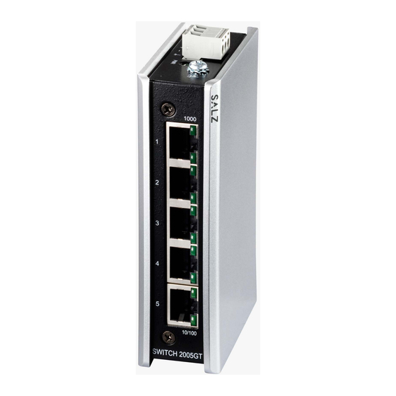
SWITCH 2005GT is equipped with 5 x 10/100/1000 RJ45 Ports
enclosed in IP30 housing.
2. Package Checklist
• SWITCH 2005GT Switch x 1
Panel view
1000
1
2
3
4
Power
5
Grounding
Screw
10/100
Top View
Front View
3. Mounting and Dismounting to DIN-Rail
ATTENTION:
!
The SWITCH 2005GT ia an open type device and
SWITCH 2005GT shall be DIN-Rail mounted in cabinet
or enclosure and the ambient temperature should not
exceed 75 °C.
-1-
Mounting the switch
Place the SWITCH 2005GT on the DIN rail from above using the
slot, push the front of the switch toward the mounting surface
until it snaps into place with a click sound.
Dismounting the switch
Press the switch from top and pull out the lower edge of the
switch and then remove the switch from the DIN rail.
Click
Mounting the Switch
4. Grounding the switch SWITCH 2005GT
Grounding and wire routing help limit the effects of noise due to
electromagnetic interference (EMI).
Step 1: Run the ground connection from the ground screw to
1000Mbps
the grounding surface prior to connecting devices.
-
Step 2: Connect the ground connection from the terminal block
to the grounding surface prior to connecting device.
ATTENTION:
!
This product is intended to be mounted to a well-
grounded mounting surface such as a metal panel.
10/100
5. Wiring requirements
WARNING:
!
Safety measures should be taken before connecting
the power cable.Turn off the power before connecting
modules or wires. The correct power supply voltage is listed on
the product label. Check the voltage of your power source to
make sure that you are using the correct voltage. DO NOT use a
voltage greater than what is specified on the product label.
Calculate the maximum possible current in each power wire and
common wire. Observe all electrical codes dictating the
maximum current allowable for each wire size. If current
exceeds the maximum rating, the wiring can overheat causing
serious damage to your equipment.
Removing the Switch
-2-
Please read and follow these guidelines:
• Use separate paths to route wiring for power and devices. If
power wiring and device wiring paths must cross make sure
the wires are perpendicular at the intersection point
NOTE: Do not run signal or communications wiring and power
wiring through the same wire conduit. To avoid interference,
wires with different signal characteristics should be routed
separately
• You can use the type of signal transmitted through a wire to
determine which wires should be kept separate. The rule of
thumb is that wiring that shares similar electrical characteris-
tics can be bundled together
• You should separate input wiring from output wiring
• We advise that you label the wiring to all devices in the system
5.1 Wiring Power Input
5.1.1 SWITCH 2005GT with 3pin terminal block
Check the polarity while connecting.
Top view of Terminal Block is shown in the figure below:
Power input terminals
Grounding terminals
Power
Grounding
Screw
Caution:
!
• Use copper conductors only
• Wiring cable temperature should support at
least 105˚C
• Tighten the wire to a torque value 20N
• The wire gauge for the terminal block should
range between 0.2 to 2.5 mm
2
-3-
Advertisement
Table of Contents

Related Manuals for SALZ 2005GT


Summary of Contents for SALZ 2005GT
- Page 1 Mounting the switch Please read and follow these guidelines: Place the SWITCH 2005GT on the DIN rail from above using the • Use separate paths to route wiring for power and devices. If SWITCH 2005GT slot, push the front of the switch toward the mounting surface power wiring and device wiring paths must cross make sure until it snaps into place with a click sound.
- Page 2 • Ports 1-5 of the switch support Gbit Ethernet (10/100/1000Base-T RJ45 Ports) • All the RJ45 ports on the SWITCH 2005GT support auto negotiation and auto MDI/MDI-X to eliminate the need for crossover cabling Note: Category 5e cable or above should be used.
Need help?
Do you have a question about the 2005GT and is the answer not in the manual?
Questions and answers