Table of Contents
Advertisement
Quick Links
SWITCH 4008GT
Quick Installation Guide
1. Overview
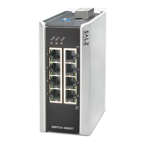
The SWITCH 4008GT Lite-Managed Industrial Ethernet Switch
is designed for harsh environments to withstand vibration,
shock, free fall, power surges. The switch is easy to set-up and
supports the critical software features required in factory automa-
tion systems such as multi-axis robots and their peripherals
(PLC's, HMI's and legacy devices). The switch includes 8-port
10/100/1000Mbps RJ45 downlink ports.
2. Package Checklist
• SWITCH 4008GT Switch x 1
Panel view
ALM
RPS
PWR
Grounding
PWR RPS ALM
Screw
1
+
PWR
Power Input
+
3
Terminal Block
RPS
5
ALM
OFF
ON
DIP Switches
ALM
7
1
1 PWR
2
2
RPS
Reset
Top View
Grounding Screw
-1-
3. Mounting and Dismounting to DIN-Rail
ATTENTION:
!
The Switch is an open type device and shall be DIN-Rail
mounted or wall mounted (optional) in the cabinet and
the ambient temperature should not exceed the operat-
ing temperature.
Mounting the switch
Place the switch on the DIN-Rail from above using the slot, push
the front of the switch toward the mounting surface until it snaps
into place with a click sound.
Dismounting the switch
Press the switch from top and pull out the lower edge of the
switch and then remove the switch from the DIN-Rail.
Mounting the Switch
ATTENTION:
!
A corrosion-free mounting rail is advisable. When
1000
installing, make sure to allow for enough space
1000Mbps
(Green)
2
between devices to properly install the cabling. And
provide ample space for air flow.
4
6
4. Grounding the switch
8
LNK/ACT
LNK/
(Green)
ACT
Grounding and wire routing help limit the effects of noise due to
electromagnetic interference (EMI). Run the ground connection
from the ground screw to the grounding surface prior to connect-
ing devices.
ATTENTION:
!
This product is intended to be mounted to a well-ground-
ed mounting surface such as a metal panel.
5. Wiring requirements
WARNING:
!
Safety measures should be taken before connecting
the power cable. Turn off the power before connecting
modules or wires. The correct power supply voltage is
listed on the product label. Check the voltage of your
power source to make sure that you are using the
correct voltage. DO NOT use a voltage greater than
Clic k
Removing the Switch
-2-
what is specified on the product label. Calculate the
maximum possible current in each power wire and
common wire. Observe all electrical codes dictating
the maximum current allowable for each wire size. If
current exceeds the maximum rating, the wiring can
overheat causing serious damage to your equipment.
Please read and follow these guidelines:
• Use separate paths to route wiring for power and devices. If
power wiring and device wiring paths must cross make sure
the wires are perpendicular at the intersection point.
NOTE: Do not run signal or communications wiring and power
wiring through the same wire conduit. To avoid interference,
wires with different signal characteristics should be routed
separately.
• You can use the type of signal transmitted through a wire to
determine which wires should be kept separate. The rule of
thumb is that wiring that shares similar electrical characteris-
tics can be bundled together
• You should separate input wiring from output wiring
• We advise that you label the wiring to all devices in the system
5.1 Wiring Power Input
You can use "PWR" for Primary Power input and "RPS" for
Redundant Power Input.
Top view of Terminal Block is shown in the figure below:
Terminal Block
Caution:
!
• Use copper conductors only
• Wiring cable temperature should support at
least 105˚C
• Tighten the wire to a torque value 20N
• The wire gauge for the terminal block should
range between 0.2 to 2.5 mm
2
To insert power wire and connect the specified voltage range at
a maximum of 0.35A DC power to the power terminal block,
follow the steps below:
1. Use a flat-head screwdriver to loosen the wire-clamp screws
2. Insert the negative/positive DC wires into the PWR-/PWR+
terminals, respectively
3. Tighten the wire-clamp screws to prevent the wires from loosen-
-3-
Advertisement
Table of Contents

Related Manuals for SALZ SWITCH 4008GT


Summary of Contents for SALZ SWITCH 4008GT
- Page 1 Place the switch on the DIN-Rail from above using the slot, push The SWITCH 4008GT Lite-Managed Industrial Ethernet Switch the wires are perpendicular at the intersection point. the front of the switch toward the mounting surface until it snaps...
- Page 2 MDI/MDI-X to eliminate the need for crossover cabling. If the equipment is used in a manner not specified by the SALZ Automation GmbH, the protection provided * Category 5e cable or above should be used. by the equipment may be impaired.
Need help?
Do you have a question about the SWITCH 4008GT and is the answer not in the manual?
Questions and answers