Table of Contents
Advertisement
STDES-WLC38WA wireless power receiver quick start guide and test report
Introduction
The
STDES-WLC38WA
reference design, based on STWLC38, is designed for wireless power receiver applications. It allows
the user to start a 2.5 W wireless charging project quickly.
It features a small size, good thermal performance, and stable power transfer.
The integrated circuit requires only few external components. The device output voltage is adjustable (the default value is 5 V).
Through an external USB-to-I²C converter, you can monitor and control the
The
STDES-WLC38WA
includes several safety mechanisms that provide overtemperature (OTP), overcurrent (OCP), and
overvoltage (OVP) protections, which can protect the device by sending an end power transfer (EPT) packet, disable the device
output, or short the receiving coil.
The
STDES-WLC38WA
reference design is ready to use with the STDES-WBC86WTX.
Figure 2.
Install the I²C drivers and the
TN1440 - Rev 2 - August 2023
For further information contact your local STMicroelectronics sales office.
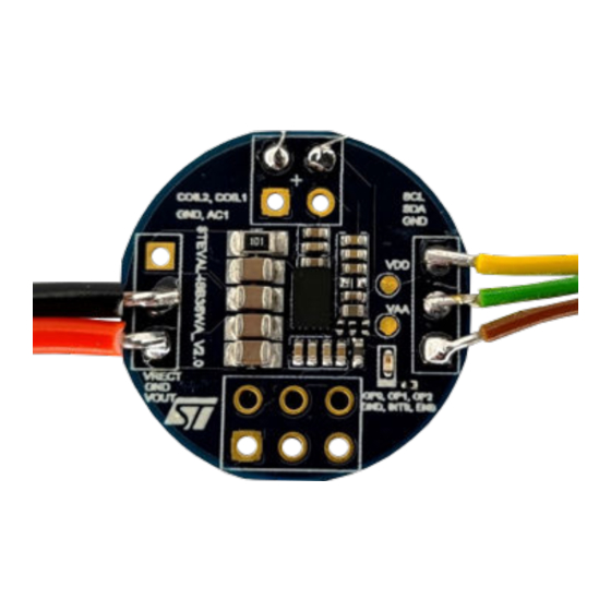
Figure 1.
STDES-WLC38WA reference design
Fully assembled board developed for
performance evaluation only,
not available for sale
STDES-WLC38WA reference design plus STDES-WBC86WTX
Fully assembled board developed for
performance evaluation only,
not available for sale
STSW-WPSTUDIO
GUI.
STWLC38
using the
STSW-WPSTUDIO
TN1440
Technical note
GUI.
www.st.com
Advertisement
Table of Contents

Related Manuals for ST STDES-WLC38WA

Summary of Contents for ST STDES-WLC38WA
-
Page 1: Figure 1. Stdes-Wlc38Wa Reference Design
TN1440 Technical note STDES-WLC38WA wireless power receiver quick start guide and test report Introduction STDES-WLC38WA reference design, based on STWLC38, is designed for wireless power receiver applications. It allows the user to start a 2.5 W wireless charging project quickly. -
Page 2: Figure 3. Stdes-Wlc38Wa Reference Design Plus Usb-To-I²C Bridge
Using an external USB-to-I²C bridge, connect the board to your PC (connector P2 on the USB-I²C bridge). This allows you to communicate with the board, program it, and monitor its functions. Figure 3. STDES-WLC38WA reference design plus USB-to-I²C bridge Fully assembled board developed for performance evaluation only, not available for sale The GUI supports MCP2221 and FT260Q-T USB-I²C converters. -
Page 3: Overview
• I²C connector, GPIO, and INT connector, SOVP resistor Figure 4. STDES-WLC38WA connection overview STDES-WLC38WA is equipped with all components necessary for a standalone operation. The coil has to be connected to pads (COIL1 and COIL2). The pad labeled as AC1 is used for debug purposes. -
Page 4: Reference Design Specifications
Reference design specifications Reference design specifications Target specification of the STDES-WLC38WA reference design are listed in the table below. Table 2. STDES-WLC38WA specifications Parameter Description RX application PCB area 20 mm RX coil specifications Inductance 11.8 µH, dimensions Φ15 mm... -
Page 5: Default Configuration
TN1440 Default configuration Default configuration Table 3. Basic parameters RX rectifier mode Full sync Minimum operating frequency 110 kHz Maximum operating frequency 205 kHz Overcurrent protection (OCP – FW/HW) 1.85 A/1.93 Overvoltage protection (OVP – FW/HW) VOUT +4 V/16 V Overtemperature protection (OVTP –... -
Page 6: Pcb Layout
TN1440 PCB layout PCB layout Figure 5. STDES-WLC38WA top layer Figure 6. STDES-WLC38WA inner1 layer TN1440 - Rev 2 page 6/19... -
Page 7: Figure 7. Stdes-Wlc38Wa Inner2 Layer
TN1440 PCB layout Figure 7. STDES-WLC38WA inner2 layer Figure 8. STDES-WLC38WA bottom layer TN1440 - Rev 2 page 7/19... -
Page 8: Typical Performance Characteristics
Rx and Tx coils was 3 mm. Note: This efficiency measurement has been performed with a Φ15 mm small Rx coil and a Φ20mm Tx coil. Figure 9. STDES-WLC38WA and STDES-WBC86WTX efficiency test TN1440 - Rev 2 page 8/19... -
Page 9: Thermal Performance
The temperature measured by the thermal-imaging camera can be different from the value measured by T RECT as the T temperature is measured inside the device. RECT Figure 10. STDES-WLC38WA thermal performance (1 of 2) Figure 11. STDES-WLC38WA thermal performance (2 of 2) TN1440 - Rev 2 page 9/19... -
Page 10: Startup Waveform
Startup waveform Startup waveform A start-up waveform of STDES-WLC38WA and STDES-WBC86WTX is shown below. The start-up conditions are center position of RX and TX coil, 3mm gap between coil and 100mA load on Rx Vout. The STDES-WBC86WTX is powered from a 5 V power supply. -
Page 11: Schematic Diagrams
Schematic diagrams Figure 13. STDES-WLC38WA circuit schematic... -
Page 12: Bill Of Materials
TN1440 Bill of materials Bill of materials Table 5. STDES-WLC38WA bill of materials Item Q.ty Ref. Value Description Manufacturer Part Number 4.7uF, 6.3V, 4.7uF, C0402, 6.3 V Wurth Elektronik 885012105008 ±10%, X5R, 0402 1µF, 6.3V, ±10%, 1uF, C0402, 6.3 V... -
Page 13: Conclusions
TN1440 Conclusions Conclusions The test results show that the STDES-WLC38WA reference design can automatically detect TX and is able to receive requested power from the STDES-STWBC86WTX transmitter board. The peak efficiency of STDES-STWBC86WTX STDES-WLC38WA is 60.23% at 2 W. At 2.5 W the efficiency is 58.24%. -
Page 14: Appendix A Reference Design Warnings, Restrictions And Disclaimer
TN1440 Reference design warnings, restrictions and disclaimer Appendix A Reference design warnings, restrictions and disclaimer Important: The reference design is not a complete product. It is intended exclusively for evaluation in laboratory/ development environments by technically qualified electronics experts who are familiar with the dangers and application risks associated with handling electrical/mechanical components, systems and subsystems. -
Page 15: Revision History
TN1440 Revision history Table 6. Document revision history Date Revision Changes 10-Mar-2023 Initial release. Modified title in cover page. 01-Aug-2023 Updated Section 6 Schematic diagrams Section 7 Bill of materials. TN1440 - Rev 2 page 15/19... -
Page 16: Table Of Contents
TN1440 Contents Contents Overview ................3 Test points . -
Page 17: List Of Tables
STDES-WLC38WA specifications ........ -
Page 18: List Of Figures
STDES-WLC38WA reference design plus STDES-WBC86WTX ........1... - Page 19 ST’s terms and conditions of sale in place at the time of order acknowledgment. Purchasers are solely responsible for the choice, selection, and use of ST products and ST assumes no liability for application assistance or the design of purchasers’...
Need help?
Do you have a question about the STDES-WLC38WA and is the answer not in the manual?
Questions and answers