Table of Contents
Advertisement
Quick Links
DESCRIPTION
Demonstration circuit 3190A-D is a high current, high
density, high efficiency open-frame μModule
tor with 45V to 65V input range. The demo board has
a
LTP™8803-1A
μModule regulator which provides
microprocessor 1.15V voltage from 54V power distri-
bution architecture with digital power system manage-
ment. The maximum output current for the demo board
is 160A. Please see LTP8803-1A data sheet for more
detailed information.
DC3190A-D powers up to default settings and produces
power based on configuration resistors without the need
for any serial bus communication. This allows easy evalu-
ation of the DC/DC converter. To fully explore the extensive
power system management features of the part, download
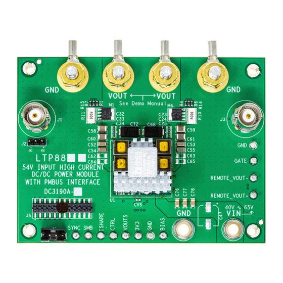
BOARD PHOTO
54V Input, High Current DC/DC Power
regula-
®
Part marking is either ink mark or laser mark
DEMO MANUAL DC3190A-D
µModule with PMBus Interface
the GUI software LTpowerPlay
2
ADI's I
C/SMBus/PMBus dongle
the board. LTpowerPlay allows the user to reconfigure the
part on-the-fly and store the configuration in EEPROM,
view telemetry of voltage, current, temperature and
fault status.
GUI Download
The software can be downloaded from:
For more details and instructions of LTpowerPlay,
please refer to LTpowerPlay GUI for LTP8803-1A Quick
Start Guide.
Design files for this circuit board are
All registered trademarks and trademarks are the property of their respective owners.
LTP8803-1A
onto your PC and use
®
DC1613A
to connect to
LTpowerPlay
available.
Rev. 0
1
Advertisement
Table of Contents

Related Manuals for Analog Devices LTP8803-1A


Summary of Contents for Analog Devices LTP8803-1A
- Page 1 The maximum output current for the demo board GUI Download is 160A. Please see LTP8803-1A data sheet for more detailed information. The software can be downloaded from: LTpowerPlay DC3190A-D powers up to default settings and produces...
-
Page 2: Performance Summary
Demonstration circuit 3190A-D is easy to set up to evalu- tablished, adjust the load current within the operating ate the performance of the LTP8803-1A. Refer to Figure 1 range of 0A to 160A max. Observe the output voltage for the proper measurement equipment setup and follow regulation, output voltage ripples, load transient re- the procedure below. -
Page 3: Quick Start Procedure
DEMO MANUAL DC3190A-D QUICK START PROCEDURE LOAD dc3190ad 3.3V 45V TO 65V – – Figure 1. Proper Measurement Equipment Setup – Figure 2. Measuring Output Voltage Ripple Rev. 0... - Page 4 CONNECTING PC TO DC3190A-D Use a PC to reconfigure the power management features current with the latest set of device drivers and docu- of the LTP8803-1A such as: nominal V , margin set mentation. The LTpowerPlay software can be downloaded...
-
Page 5: Typical Performance Characteristics
BIAS 1.15V 1.3V 100 120 140 160 LOAD CURRENT (A) dc3190ad F03 Figure 4. Measured LTP8803-1A Efficiency at V = 54V, f = 600kHz, Forced Air Cooled with 900LFM Figure 5. LTP8803-1A Thermal Performance at V = 54V, I = 160A, T = 25°C, 500LFM Forced Airflow... - Page 6 0A TO 20A/DIV 10mV/DIV dc3190ad F07 100 s/DIV = 57.50mV OUT(PK-PK) Figure 7. LTP8803-1A Load Transient Responses with Load Steps 0A to 40A to 0A at dI/dt = 40A/µs 5mV/DIV dc3190ad F08 1 s/DIV = 4.22mV OUT(PK-PK) Figure 8. LTP8803-1A Output Voltage Ripple Measured through J3 (54V Input, I = 160A, 20MHz BW Limit) Rev.
-
Page 7: Parts List
PANASONIC, EEFGX0D561R 20%, 7343 CAP ., 100pF, X7R, 16V, 10%, 0603 AVX, 0603YC101KAT2A J6-J9 EVAL BOARD STUD HARDWARE SET, #10-32 ANALOG DEVICES, 720-0010 LABEL SPEC, DEMO BOARD SERIAL NUMBER BRADY, THT-96-717-10 M1-M4 XSTR., MOSFET, N-CH, 25V, 70A, LFPAK55, NEXPERIA, PSMN5R4-25YLDX Power-SO8 R1-R4 RES., 24.9Ω, 1%, 1/10W, 0603, AEC-Q200... - Page 8 DEMO MANUAL DC3190A-D PARTS LIST ITEM REFERENCE PART DESCRIPTION MANUFACTURER/PART NUMBER Hardware: For Demo Board Only E3-E14 TEST POINT, TURRET, 0.064" MTG. HOLE, MILL-MAX, 2308-2-00-80-00-00-07-0 PCB 0.062" THK J1, J3 CONN., RF , BNC, RCPT, JACK, 5-PIN, ST, AMPHENOL RF , 112404 THT, 50Ω...
-
Page 9: Schematic Diagram
Devices for its use, nor for any infringements of patents or other rights of third parties that may result from its use. Specifications subject to change without notice. No license is granted by implication or otherwise under any patent or patent rights of Analog Devices. -
Page 10: Revision History
Board until you have read and agreed to the Agreement. Your use of the Evaluation Board shall signify your acceptance of the Agreement. This Agreement is made by and between you (“Customer”) and Analog Devices, Inc. (“ADI”), with its principal place of business at One Technology Way, Norwood, MA 02062, USA. Subject to the terms and conditions of the Agreement, ADI hereby grants to Customer a free, limited, personal, temporary, non-exclusive, non-sublicensable, non-transferable license to use the Evaluation Board FOR EVALUATION PURPOSES ONLY.
Need help?
Do you have a question about the LTP8803-1A and is the answer not in the manual?
Questions and answers