Table of Contents
Advertisement
Quick Links
One Technology Way • P.O. Box 9106 • Norwood, MA 02062-9106, U.S.A. • Tel: 781.329.4700 • Fax: 781.461.3113 • www.analog.com
Evaluating the
AD5758
FEATURES
Full featured evaluation board for the
On-board 2.5 V
ADR4525
reference
On-board
ADP1031-1
isolated PMU with integrated
SPI signal isolation channels
ACE
software for control
EVALUATION KIT CONTENTS
EVAL-AD5758SDZ evaluation board
EQUIPMENT NEEDED
EVAL-SDP-CS1Z
board
Bench top power supply and connector cables
ADDITIONAL DOCUMENTS REQUIRED
AD5758
data sheet
ACE User Manual
SOFTWARE REQUIRED
ACE
software for control
PLEASE SEE THE LAST PAGE FOR AN IMPORTANT
WARNING AND LEGAL TERMS AND CONDITIONS.
Single-Channel, 16-Bit Current and Voltage Output DAC with
Dynamic Power Control and HART Connectivity
AD5758
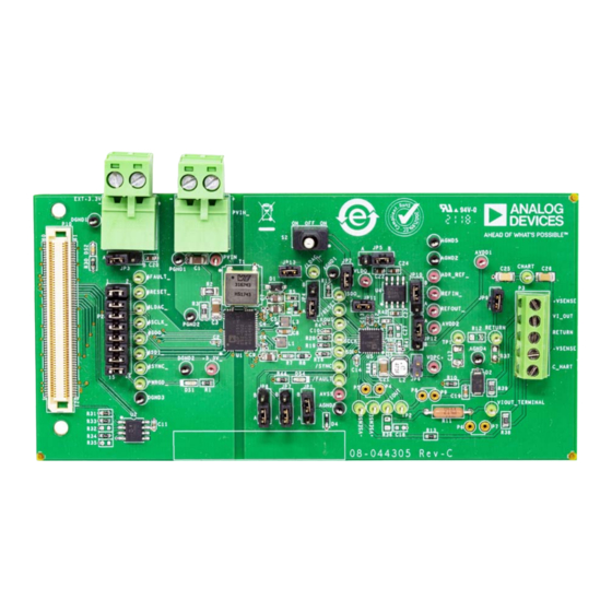
EVALUATION BOARD PHOTOGRAPH
Figure 1. EVAL-AD5758SDZ Evaluation Board
EVAL-AD5758
GENERAL DESCRIPTION
This user guide describes the evaluation board for the AD5758,
a single-channel, voltage and current output, digital-to-analog
converter (DAC) with on-chip dynamic power control (DPC) to
minimize package power dissipation.
For full details, refer to the
sheet when using the EVAL-AD5758SDZ. The configuration of
the various link options is explained in the Evaluation Board
Hardware section. The installation of the companion software is
discussed in the Evaluation Software Quick Start Procedures
section.
The EVAL-AD5758SDZ, as shown in Figure 1, requires the
EVAL-SDP-CS1Z
the USB port of the PC via the
Analysis|Control|Evaluation (ACE)
programming of the AD5758, and is available with the EVAL-
AD5758SDZ evaluation board.
Rev. A | Page 1 of 22
User Guide
AD5758
data sheet. Consult the data
board. The EVAL-AD5758SDZ interfaces to
EVAL-SDP-CS1Z
software allows simplified
UG-1268
board. The
Advertisement
Table of Contents

Related Manuals for Analog Devices EVAL-AD5758


Summary of Contents for Analog Devices EVAL-AD5758
-
Page 1: Features
EVAL-AD5758 User Guide UG-1268 One Technology Way • P.O. Box 9106 • Norwood, MA 02062-9106, U.S.A. • Tel: 781.329.4700 • Fax: 781.461.3113 • www.analog.com Evaluating the AD5758 Single-Channel, 16-Bit Current and Voltage Output DAC with Dynamic Power Control and HART Connectivity... -
Page 2: Table Of Contents
UG-1268 EVAL-AD5758 User Guide TABLE OF CONTENTS Features ....................1 Initial Setup ..................5 Evaluation Kit Contents ..............1 AD5758 Block Diagram and Functions ..........7 Equipment Needed ................1 Initial Configuration ..............9 Additional Documents Required ........... 1 DC-to-DC Converter Settings .............9... -
Page 3: Evaluation Board Hardware
EVAL-AD5758 User Guide UG-1268 EVALUATION BOARD HARDWARE POWER SUPPLIES SERIAL COMMUNICATION The EVAL-AD5758SDZ evaluation board contains the ADP1031-1 SDP-S system demonstration platform handles commu- power management unit (PMU), which generates three of four nication to the EVAL-AD5758SDZ via the PC. By default, the power supply inputs required by the AD5758: AV (+26.7 V),... -
Page 4: Changes To Table 2
UG-1268 EVAL-AD5758 User Guide Table 2. Link Options for the P2_ Header Pin No. Position Function 1, 2 Inserted Connects the FAULT signal from the SDP-S to the MGP03 pin on the ADP1031-1. Not inserted Disconnects the FAULT signal from the... -
Page 5: Evaluation Software Quick Start Procedures
PLUG-INS in appears as shown in Figure 3, click the button that is circled The EVAL-AD5758SDZ software uses the Analog Devices, Inc., in red in Figure 3. After clicking this button, the pop-up software. For instructions the use of the software, see window shown in Figure 4 appears. -
Page 6: Changes To Figure 7
UG-1268 EVAL-AD5758 User Guide Double-click EVAL-AD5758SDZ to open the AD5758 block Writing the initial configuration values clears these error diagram (see Figure 7). The INITIAL CONFIGURATION flags. If the device is power cycled, or if the USB cable is pane appears on the left side of the window. Several register... -
Page 7: Changes To Figure 8 And Table 3
EVAL-AD5758 User Guide UG-1268 AD5758 BLOCK DIAGRAM AND FUNCTIONS AD5758 ACE block diagram, as shown in Figure 8, appears A full description of each block and register setting is available similar to the block diagram shown in the AD5758 data sheet for... -
Page 8: Changes To Table 4
UG-1268 EVAL-AD5758 User Guide Label Function Description The Two Stage Readback pane initiates two-stage readback through the two-stage readback select register. Click Readback to initiate a write to the two-stage readback select register and issue a NOP command. In the DIGITAL DIAGNOSTIC RESULTS pane, click Update and Readback Digital Diagnostic Result button to trigger a write 1 to clear operation and initiate a readback from the digital diagnostic result register. -
Page 9: Changes To Figure 10
EVAL-AD5758 User Guide UG-1268 Figure 9. AD5758 Memory Map in the Software INITIAL CONFIGURATION An initial configuration wizard is available when opening the AD5758 plug-in. The initial configuration wizard allows quick configuration of the AD5758 and provides configuration of the clock output in the general-purpose configuration register, the dc-to-dc settings, DAC configuration, and the DAC input register. -
Page 10: Changes To Setting The Dac Output Section, Figure 11, Writing To The Configuration Register Section, Figure 12, Figure 13, And Figure 14
UG-1268 EVAL-AD5758 User Guide SETTING THE DAC OUTPUT To configure the DAC output, use the DAC Config Register pop- up menu (see Figure 11). Click the 16 Bit DAC block in the block diagram to display the DAC configuration register. Select the appropriate settings, and then click Apply Changes. -
Page 11: Changes To Figure 15
EVAL-AD5758 User Guide UG-1268 EXAMPLE CONFIGURATION SEQUENCES Several example configuration sequences are available. Click Example Sequences, and the window shown in Figure 15 appears. To enable any of the sequences, click the relevant sequence button, as shown in Figure 16. The sequence runs immediately and the output changes accordingly. -
Page 12: Changes To Figure 16
UG-1268 EVAL-AD5758 User Guide Figure 16. Selecting an Example Sequence Rev. A | Page 12 of 22... -
Page 13: Ace Tool Views
EVAL-AD5758 User Guide UG-1268 TOOL VIEWS software provides additional functionality to the main REGISTER DEBUGGER TOOL view described in this user guide. Open these views from the View Use the register debugger tool to perform raw writes to and menu on the application toolbar. The software features a reads from the device. -
Page 14: Evaluation Board Schematics And Artwork
UG-1268 EVAL-AD5758 User Guide EVALUATION BOARD SCHEMATICS AND ARTWORK Figure 17. AD5758 Schematic Rev. A | Page 14 of 22... -
Page 15: Changes To Figure 18
EVAL-AD5758 User Guide UG-1268 Figure 18. AD5758 Supplies and Reference Options Schematic Rev. A | Page 15 of 22... -
Page 16: Changes To Figure 19
UG-1268 EVAL-AD5758 User Guide 3.3V_SDP 0.1UF 3.3V_SDP DGND 100K RESET_IN_N BMODE1 DGND 100K UART_RX UART_TX SDP DEBUG LED RESET_OUT_N SLEEP_N EEPROM_A0 WAKE_N 100K 100K DGND DGND 24LC32A/SN DGND CLKOUT DGND TMR_C TMR_D TMR_A TMR_B GPIO6 GPIO7 GPIO4 GPIO5 /FAULT_SDP SDP_PWRGD... -
Page 17: Changes To Figure 20
EVAL-AD5758 User Guide UG-1268 +VSENSE +VSENSE GOLD PINS FOR RESISTOR 2.0K VIOUT VIOUT_TERMINAL +VSENSE VIOUT VI_OUT RETURN -VSENSE C_HART 0.01UF SMAJ33CA-TR THROUGH-HOLE LOAD RESISTOR OPTION 0.01UF AGND AGND AGND RETURN 2.0K 1.0UF AGND 2.0K –VSENSE AGND AGND –VSENSE CHART CHART 0.047UF... -
Page 18: Deleted Figure 21 And Figure 22; Renumbered Sequentially
UG-1268 EVAL-AD5758 User Guide Figure 21. ADP1031-1 PMU Schematic Rev. A | Page 18 of 22... -
Page 19: Deleted Figure 23 And Figure 24
EVAL-AD5758 User Guide UG-1268 Figure 22. EVAL-AD5758, Silkscreen Figure 23. EVAL-AD5758, Primary Layer Figure 24. EVAL-AD5758 Ground Planes, Layer 2 Rev. A | Page 19 of 22... -
Page 20: Added Figure 25 And Figure 26
UG-1268 EVAL-AD5758 User Guide Figure 25. EVAL-AD5758 Ground and Power Plane, Layer 3 Figure 26. EVAL-AD5758, Layer 4 (Secondary) Rev. A | Page 20 of 22... -
Page 21: Ordering Information
EVAL-AD5758 User Guide UG-1268 ORDERING INFORMATION BILL OF MATERIALS Table 5. Bill of Materials Reference Designator Description Manufacturer Part Number Test point, green Vero Technologies 20-313138 #FAULT_, #LDAC_, #RESET_, #SCLK_, #SDI_, #SDO_, #SYNC_, +VSENSE, VSENSE, /FAULT_, /LDAC_, /RESET_, /SYNC_, CHART, CLKOUT_,... - Page 22 By using the evaluation board discussed herein (together with any tools, components documentation or support materials, the “Evaluation Board”), you are agreeing to be bound by the terms and conditions set forth below (“Agreement”) unless you have purchased the Evaluation Board, in which case the Analog Devices Standard Terms and Conditions of Sale shall govern. Do not use the Evaluation Board until you have read and agreed to the Agreement.
Need help?
Do you have a question about the EVAL-AD5758 and is the answer not in the manual?
Questions and answers