
Related Manuals for Analog Devices ADIS1700 Series


Summary of Contents for Analog Devices ADIS1700 Series
- Page 1 ADIS1700x Vision-Sensing Camera Module User Guide (includes ADIS17001 and ADIS17002) Revision 1.0, October 2017 Part Number 82-100136-01 Analog Devices, Inc. One Technology Way Norwood, MA 02062-9106...
- Page 2 Analog Devices, Inc. reserves the right to change this product without prior notice. Information furnished by Ana- log Devices is believed to be accurate and reliable. However, no responsibility is assumed by Analog Devices for its use; nor for any infringement of patents or other rights of third parties which may result from its use. No license is granted by implication or otherwise under the patent rights of Analog Devices, Inc.
-
Page 3: Table Of Contents
Product Overview ............................1–1 Purpose of This Manual..........................1–1 Intended Audience............................1–2 Technical Support ............................1–2 Product Information ............................1–3 Analog Devices Website..........................1–3 EngineerZone ............................. 1–3 Notation Conventions ........................... 1–3 ADIS1700x Functional Description SNAP Framework Overview .......................... 2–1 System Overview ............................2–1 Block Diagram............................... - Page 4 GetDeviceInfo ............................5–2 GetDeviceStatus ............................5–2 UpdateApplicationFirmware........................5–2 UpdateBootloaderFirmware........................5–2 CreateRestorePoint ............................. 5–2 RecoverRestorePoint........................... 5–3 ContinuousVideoRecorder ......................... 5–3 RandomFrameVideoRecorder ........................5–3 CaptureLoop .............................. 5–3 MultiSensorCaptureLoop ........................... 5–3 UserCaptureLoop ............................5–4 ADIS1700xAPIConsole..........................5–4 ADIS1700xGetConfig..........................5–4 ADIS1700xCaptureLoop..........................5–4 ADIS1700xMultiSensorCaptureLoop......................5–4 ADIS1700xUserCaptureLoop........................5–5 SNAP Development Libraries........................
- Page 5 Smart Camera Mode ..........................5–8 Configuration Mode..........................5–8 Bootloader Mode............................. 5–9 ADVS200x Luminance Image ........................5–9 Displayed Image Enhancement ....................... 5–9 Displayed Image Negation ........................5–10 Image Histogram........................... 5–10 Configuring the ADVS200x ........................5–12 Modifying ADVS200x Parameters......................5–12 Setting the Defaut ADVS200x Parameters ..................5–13 Saving and Loading ADVS200x Parameters ..................
- Page 6 CreateADIS1700xApplication ........................6–1 Connect..............................6–2 Disconnect ..............................6–2 Ping................................6–2 GetSoftwareVersion ............................ 6–2 Application Level Data........................... 6–2 GetLedStatus .............................. 6–3 SetLedStatus ............................... 6–3 IMU Service ..............................6–3 GetConfiguration ............................6–3 GetMeasurements............................6–4 ADVS200x Camera Service..........................6–5 GetADVS200xRegisters..........................6–5 SetADVS200xRegisters..........................6–5 GetADVS200xLut ............................
- Page 7 Clear Sections............................7–14 Read Section............................7–15 Write Section............................7–16 Validate Section ............................. 7–17 Create/Recover Restore Point ........................ 7–18 Application Firmware ..........................7–19 Main Application Messages ........................7–19 Get Mode .............................. 7–21 Set Mode ............................... 7–22 Store/Restore Parameters to Flash ......................7–23 Get Production Parameters ........................
- Page 8 Set Configuration..........................7–53 Get Parameters ............................7–55 Set Parameters............................7–57 Storage Module Messages ......................... 7–58 Get Device Info ............................. 7–59 Clear Sections............................7–60 Read Section............................7–61 Write Section............................7–62 Validate Section ............................. 7–63 Get Log Data Summary ........................7–65 Get Log Data ............................7–66 Clear Log Data............................
-
Page 9: Preface
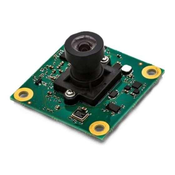
Preface 1 Preface Thank you for purchasing the Analog Devices, Inc. ADIS1700x Vision-Sensing Camera Module development kit. The ADIS1700x is a low-power vision-sensing camera module in a small form factor for interfacing to USB 2.0 HOST-compliant devices including single board computers. It includes a tri-axial accelerometer for image stabiliza- tion, tilt and impact detection. -
Page 10: Intended Audience
Intended Audience Intended Audience The primary audience for this manual is a programmer who is familiar with the Analog Devices Blackfin+ ADSP- BF70x processor and ADVS200x imager. For additional information about the Analog Devices camera module, see the ADIS17001/ADIS17002 Low Power, Small Form Factor Vision-Sensing Camera Module Data Sheet. -
Page 11: Product Information
If you are a registered user, just log on. Your user name is your e-mail address. EngineerZone EngineerZone is a technical support forum from Analog Devices, Inc. It allows you direct access to ADI technical support engineers. You can search FAQs and technical information to get quick answers to your embedded process- ing and DSP design questions. - Page 12 Notation Conventions Example Description {this | that} Alternative required items in syntax descriptions appear within curly brackets and separated by vertical bars; read the example as this or that. One or the other is required. [this | that] Optional items in syntax descriptions appear within brackets and separated by vertical bars;...
-
Page 13: Adis1700X Functional Description
ADIS1700x Functional Description 2 ADIS1700x Functional Description This chapter describes how the ADIS1700x interfaces with functional blocks and the SNAP Framework. SNAP Framework Overview The SNAP Framework is a set of libraries that enable the user to quickly develop applications for the Blackfin pro- cessor. -
Page 14: Block Diagram
Block Diagram Host Libraries and Application LIBRARY APPLICATION ICE 2000/ PC WITH USB PORTS ICE1000 EPPI SNAP SENSOR SNAP Framework WITH CAMERA 32MB SPI FLASH LP-DDR ACCELEROMETER MEMORY MEMORY Figure 2-1: ADIS1700x Software System Block Diagram Block Diagram The ADIS1700x Block Diagram shows the functional blocks of the ADIS1700x Vision-Sensing Camera Module. BOOT FLASH LPDDR SRAM 10KV... -
Page 15: Using The Adis1700X
• CrossCore Embedded Studio – Perpetual License (restricted use for ADIS1700x) • 67° FOV and 110° HFOV Lenses Contact the vendor where you purchased the evaluation board or contact Analog Devices, Inc if any item is missing. Default Configuration The ADIS1700x is designed to run as a standalone unit. -
Page 16: Board Installation
Board Installation damage can occur on devices subjected to high energy ESD. Therefore, proper ESD precautions should be taken to avoid performance degradation or loss of functionality. Board Installation Complete the following steps to set up the hardware. 1. Connect the ADIS1700x board from the adapter shown in the ADIS1700x Evaluation Board to a USB port of a PC using the supplied USB cable. -
Page 17: Installation
1. Connect the device to the PC through the USB port. Windows starts searching for the driver. 2. Stop the automatic search and select the option for manually locating the driver. 3. Point to the driver folder (C:\Analog Devices\SnapSensorLibrary\Drivers\ADI WinUSB). ADIS1700x Vision-Sensing Camera Module User Guide 4–1... -
Page 18: Uninstall Snap Sensor Library
Uninstall SNAP Sensor Library Uninstall SNAP Sensor Library Complete the following steps to uninstall the SNAP Sensor library application. 1. Run the Windows Control Panel. 2. Select Uninstall or change a Program. 3. Select the item (for example, SnapSensorLibrary (Development)) and click Uninstall 4. - Page 19 Create a Win32 Project 9. Modify the project properties to link to the library files. In the Linker settings, copy and paste $(SnapSensorLi- brary_LibPath) Include to Additional Include Directories. In the Linker settings, Additional Dependencies must have at least SnapCoreLib.lib and can also contain one or more of the following libraries depending upon the application to be built: a.
-
Page 20: Demo Applications
Demo Applications 5 Demo Applications The ADIS1700x Vision-Sensing Camera Module demo and development packages are supported by the following applications: • ADVS200x Demo Application – an application that demonstrates the capability of the ADVS200x sensor. See the ADVS200x Demo User Guide for details. •... -
Page 21: Getdeviceinfo
SnapSensorLibrary • Connects to a device running the SNAP Framework • Downloads and displays the device bootloader firmware version • Downloads and displays the device application firmware versions GetDeviceInfo GetDeviceInfo is a console application that has the following features: • Connects to a device running the SNAP Framework •... -
Page 22: Recoverrestorepoint
SnapSensorLibrary • Connects to a device running the SNAP Framework • Copies the current application firmware and data into the restore point section of the flash RecoverRestorePoint RecoverRestorePoint is a console application that has the following features: • Connects to a device running the SNAP Framework •... -
Page 23: Usercaptureloop
SnapSensorLibrary NOTE: This console application is only available with the development installer. UserCaptureLoop UserCaptureLoop is a console application that has the following features: • Connects to a device running the SNAP Framework • Continuously downloads the image data from each of the ADVS200x sensors in a loop running in the main program thread NOTE: This console application is only available with the development installer. -
Page 24: Adis1700Xusercaptureloop
SnapSensorLibrary • Continuously downloads the image data and IMU data from each of the ADIS1700x in loops that run in sepa- rate threads NOTE: This console application is only available with the development installer. ADIS1700xUserCaptureLoop ADIS1700xUserCaptureLoop is a console application that has the following features: •... -
Page 25: Snapsensorconnectionlib
SNAP Development Libraries • Converts 10-bit images to 8-bit display images with or without image enhancement • Saves images into bitmap files SnapSensorConnectionLib The SnapSensorConnectionLib library is used to connect and communicate with a device and read or write to the flash storage on the device. The library includes the following functionality: •... -
Page 26: User Interface
ADIS1700x Demo Application • Updates the firmware of the device User Interface The User Interface figure shows the different sections of the user interface. Figure 5-1: User Interface Connecting to the Device The following sections describe the steps to connect to the ADIS1700x. •... -
Page 27: Close A Connection
Connecting to the Device 2. From the User Interface Main Menu select Image source>Open>ADIS1700x on USB..The application starts a discovery process to find all the devices connected to the PC. A list of connected devi- ces is displayed. 3. Select the device in the list and click Select. Close a Connection Complete the following step to close a connection. -
Page 28: Bootloader Mode
Operating Modes Bootloader Mode In bootloader mode, a “bootloader” firmware starts running on the ADIS1700x device. The ADVS200x sensor and IMU are not accessed. This mode is used by the PC application to allow the user to upload new firmware. ADVS200x Luminance Image The ADIS1700x delivers luminance images captured from the on-board ADVS200x sensor. -
Page 29: Displayed Image Negation
ADVS200x Luminance Image Displayed Image Negation The luminance image has a value of 0 for the brightest pixel and a value of 1023 for the darkest pixel. Luminance value is an indicator of the time for the pixel to reach a reference voltage. A pixel exposed to a bright light reaches the reference voltage in a shorter period of time and therefore its value is small. - Page 30 ADVS200x Luminance Image Figure 5-2: Histogram Example Using Spread It is possible to select a window in the histogram for displaying the image. Edit the Spread parameters to modify a window. The width of the window is defined by the Spread Bits value. The position of the window in the histogram is defined by the Spread Min value.
-
Page 31: Configuring The Advs200X
ADIS1700x Demo Application Figure 5-3: Histogram Using Spread Configuring the ADVS200x The following tasks are associated with configuring the ADVS200x: • Modifying ADVS200x Parameters • Saving and Loading ADVS200x Parameters Modifying ADVS200x Parameters The following steps describe how to edit the ADVS200x parameters. 1. -
Page 32: Setting The Defaut Advs200X Parameters
Modifying ADVS200x Parameters 2. In the configuration panel select the Commisioning and Parameters tab. 3. Select the ADVS200x tab. 4. Modify the parameters, as required. 5. Click Upload icon to upload the ADVS200x parameters to the ADIS1700x device. 6. Click Yes when requested to save the data on the device flash. 7. - Page 33 Modifying ADVS200x Parameters 2. In the configuration panel select the Commissioning and Parameters tab. 3. Select the ADVS200x tab. 4. Click Set default ADVS200x. 5. Click Upload to upload the ADVS200x parameters to the ADIS1700x device. 5–14 ADIS1700x Vision-Sensing Camera Module User Guide...
-
Page 34: Saving And Loading Advs200X Parameters
Configuring the ADVS200x 6. Click Yes when requested to save the data on the ADIS1700x device flash. 7. Select Smart Camera mode. Saving and Loading ADVS200x Parameters Complete the following steps to save the ADVS200x parameters to a file: Load the ADVS200x Parameters from a file Save the ADVS200x Parameters to a file... -
Page 35: Save The Advs200X Parameters
Saving and Loading ADVS200x Parameters 4. Click Upload to upload the ADVS200x parameters to the device. 5. Click Yes when requested to save the data on the device flash. 6. Select Smart Camera mode. Save the ADVS200x Parameters Complete the following steps to save the ADVS200x parameters to a file: 1. -
Page 36: Accelerometer Axis Measurement
ADIS1700x Demo Application 3. Select the ADVS200x tab. 4. Click the Save to file icon. 5. Select Smart Camera mode. Accelerometer Axis Measurement The ADIS1700x delivers axis measurements from the on-board accelerometer. Measurements are collected at a pre- defined sample rate and then down-sampled by averaging before making them available to the host application. In the Smart Camera mode, the ADIS1700x Demo application continuously polls for these measurements and dis- plays them in the User Interface... -
Page 37: Tab Display
Accelerometer Axis Measurement Figure 5-4: Graphical Display Tab Display The measurements are displayed as a table of values when the Graph option is unselected. The table is updated each time the measurements are polled by the ADIS1700x Demo application. 5–18 ADIS1700x Vision-Sensing Camera Module User Guide... -
Page 38: Modifying Imu Parameters
ADIS1700x Demo Application Figure 5-5: Tabular Display Modifying IMU Parameters The following steps describe how to edit the IMU configuration parameters. 1. Select Configuration mode. Switching modes can take a few seconds. NOTE: 2. In the configuration panel select the Commissioning and Parameters tab. ADIS1700x Vision-Sensing Camera Module User Guide 5–19... -
Page 39: Updating Firmware
ADIS1700x Demo Application 3. Select the IMU tab. 4. Modify the parameters, as required. a. Choose the Accelerometer tab to edit the accelerometer offsets, ranges and filter values. 5. Click Upload to upload the IMU parameters to the ADIS1700x device. 6. -
Page 40: Update Bootloader Firmware
Updating Firmware Update Bootloader Firmware The following steps describe how to update the bootloader firmware. 1. Select Bootloader mode. 2. Select the Firmware tab. 3. Click Update bootloader. 4. Select the firmware file (for example, ADIS1700x_Bootloader_vXX.ldr for ADIS1700x). Update Application Firmware The following steps describe how to update the application firmware. -
Page 41: Recovering From A Restore Point
Update Application Firmware 4. Select the firmware file (for example, ADIS1700x_application_vxx.ldr for ADIS1700x). Recovering from a Restore Point Complete the following steps to recover the original firmware application and its associated data. 1. Select Bootloader mode. 2. Select the Firmware tab. 3. -
Page 42: Imgseqfile Viewer Application
ImgSeqFile Viewer Application 4. Click ADIS1700x for the Device type. CAUTION: Select the correct device type. Otherwise, the device could be re-programmed incor- rectly and may become unusable without re-programming through a JTAG connector. 5. Click Continue. Device discovery begins. 6. -
Page 43: Advs200X Parameters Editor Application
ADVS200x Parameters Editor Application ADVS200x Parameters Editor Application The ADVS200x Parameters Editor application is a UI application that allows the user to: • Edit the ADVS200x configuration parameters • Read and write the ADVS200x parameters to a file This application does not require that the device be connected to run. This application is available only with the development installer. -
Page 44: Adis1700X Library
ADIS1700x Library 6 ADIS1700x Library The ADIS1700x library is used to communicate between the host computer and the ADIS1700x. The library con- sists of APIs for the following functions: • Device Discovery and Initialization — Discover and connect to devices that are running the SNAP Framework and ADIS1700x application firmware •... -
Page 45: Connect
Device Discovery and Initialization ADIS1700xConnectionFactory Parameters The FrameworkDevice objects found in discovery process Connect Establishes a communication channel to the ADIS1700x device Class ADIS1700xApplication Disconnect Closes the communication channel to the ADIS1700x device Class ADIS1700xApplication Ping The host sends a Ping message to the ADIS1700x device to check if the communication is alive. The device sends back an Acknowledge (ACK) message. -
Page 46: Getledstatus
Application Level Data GetLedStatus Returns the status of the on-board LEDs Class ADIS1700xApplication Returns Led status of LEDs present Parameters An array LedStatus structures. Each LedStatus object represents the status of one LED and consists of the: • LED ID •... -
Page 47: Getmeasurements
IMU Service NOTE: Measurements are collected from the accelerometer at a higher rate (1KHz) and the data is downsampled to the configuration value. Currently, this value is 100Hz. • Accelerometer X-axis range: (32-bit integer value representing mg) • Accelerometer Y-axis range •... -
Page 48: Advs200X Camera Service
ADVS200x Camera Service • An array of 16-bit accelerometer X measurements (if requested) • An array of 16-bit accelerometer Y measurements (if requested) • An array of 16-bit accelerometer Z measurements (if requested) ADVS200x Camera Service The APIs defined in this section are used for servicing the camera. GetADVS200xRegisters Returns the values of the ADVS200x imager registers Class... -
Page 49: Setadvs200Xlut
ADVS200x Camera Service The LUT values are filled up in the object SetADVS200xLut Sets the values of the ADVS200x imager look-up table Class CameraModule Parameters The IADVS200x Lut interface to an object containing ADVS200x imager LUT values GetLuminanceImage Returns the last captured luminance image Class CameraModule Returns... -
Page 50: Communication Protocol
Communication Protocol 7 Communication Protocol The ADIS1700x communication protocol, also known as the SNAP Protocol, provides the interface between the ADVS200x imager and the host PC. The protocol can be used to integrate other sensors and modules. It is part of the ecosystem available to develop embedded applications built around the ADVS200x sensor. -
Page 51: Architecture Description
Architecture Description Architecture Description The SNAP protocol uses a master/slave architecture. Messages from the master to the slave are called commands; messages from the slave to the master are called responses. The communication sequence is always initiated by the master. The master sends a command; the slave acknowledg- es the command and then sends the response. -
Page 52: Message Layer
Architecture Description The Ping, ACK and NACK messages are sent to the host once the transport layer has been decoded and verified by the device. The verification is based only on the consistency of the two error-detecting codes (the last two fields in the header). - Page 53 Architecture Description Table 7-4: Message Layer Header - Response (Continued) Field Name Type Notes Response ID Identical to the respective command Version Version of the response ID Reserved2 Set to 0 Payload Size Result Status In the firmware architecture, the protocol handling is distributed. Every module is responsible for its messages. The module ID gives the communication module a way to dispatch messages to each module.
-
Page 54: Operational Modes
Architecture Description Table 7-6: Reserved Command IDs Command ID Description 0x00 Factory Reset 0x01 Reset 0x02 Reserved 0x03 Module SW Version 0x04 to 0xF Reserved Table 7-7: Reserved Results Status Module ID Reserved Result Status Notes 0x00 0x01 Module ID Not Present 0x02 Invalid Version 0x03... -
Page 55: Bootloader Firmware
Bootloader Firmware When the device cannot execute a command due to an invalid mode, a response with the Result Status field set to 0x06 Command Unavailable is sent to the host. Bootloader BOOTLOADER MODE No message ever received Last message received 1 min ago Boot Failed Set Mode Boot tried 10 min ago... -
Page 56: Bootloader Messages
Bootloader Firmware • Allows the user to upgrade the factory application firmware with a new firmware (in this case, the factory firm- ware is not deleted but used as backup). • Restores the factory application firmware if something goes wrong during the upgrade •... -
Page 57: Reset
Bootloader Messages 1. Clear the associated section (Clear Sections) 2. Upload the data (use multiple Write Sections) 3. Validate the section (Validate Section) Reset The bootloader software triggers a hardware reset; the device boots from FLASH (first sector). C++ API: SnapSensor::SensorConnection::ApplicationModule::Reset() Table 7-9: Reset Header - Command Field Name... -
Page 58: Get Device Status
Bootloader Messages Table 7-11: SW Version Command - Header Field Name Type Notes Module ID Reserved1 Command ID 0x03 Version Reserved2 Payload Size Reserved3 Table 7-12: SW Version Response- Header Field Name Type Notes Module ID Reserved1 Command ID 0x03 Version Reserved2 Payload Size... -
Page 59: Get Device Info
Bootloader Messages Table 7-14: Get Device Status Command - Header Field Name Type Notes Module ID Reserved1 Command ID 0x09 Version Reserved2 Payload Size Reserved3 Table 7-15: Get Device Status Response- Header Field Name Type Notes Module ID Reserved1 Command ID 0x09 Version Reserved2... - Page 60 Bootloader Messages Table 7-17: Get Device Info Command - Header Field Name Type Notes Module ID Reserved1 Command ID 0x10 Version Reserved2 Payload Size Reserved3 Table 7-18: Get Device Info Response - Header Field Name Type Notes Module ID Reserved1 Command ID 0x10 Version...
-
Page 61: Set Device Info
Bootloader Messages Set Device Info The Set Device Info message is used to save to a persistent memory (generally FLASH) information such as device serial number (unique device identification), device name and manufacturer, and user-defined metadata. C++ API: void SnapSensor::SensorConnection::ApplicationModule:: SetDeviceInfo(DeviceInfo *deviceInfo) Table 7-20: Set Device Info Command - Header Field Name... -
Page 62: Get Sections Info
Bootloader Messages Table 7-22: Set Device Info Response - Header (Continued) Field Name Type Notes Command ID 0x14 Version Reserved2 Payload Size Result Status Get Sections Info The Get Sections Info command returns a list of the sections in the non-volatile computer storage medium with its size and offset. -
Page 63: Clear Sections
Bootloader Messages Table 7-25: Get Sections Info Response - Payload Field Name Type Notes Sector Length Length of the smaller erasable area in the storage medium in bytes. Offsets and sizes are expressed in terms of sectors. Num Sections × N Section data Offset [Sectors] Size [Sectors]... -
Page 64: Read Section
Bootloader Messages Table 7-28: Clear Sections Response- Header (Continued) Field Name Type Notes Version Reserved2 Payload Size Result Status Read Section Reads a section. Offset and size are expected to be expressed in sectors. The sector size is provided by the Get Sec- tions Info message. -
Page 65: Write Section
Bootloader Messages Table 7-32: Read Section Response - Payload Field Name Type Notes Offset [sectors] Num Sections N; where N cannot exceed 8 Data M = N × Sector Size Write Section The Write Section command writes a section. Each response returns the data that was read back after the write oper- ation (cache disabled). -
Page 66: Validate Section
Bootloader Messages Table 7-35: Write Section Response- Header (Continued) Field Name Type Notes Payload Size 12 + Size Result Status Table 7-36: Write Section Response - Payload Field Name Type Notes Section ID Offset [sectors] Size [sectors] Number of sectors N; where N cannot exceed 8 M ≤... -
Page 67: Create/Recover Restore Point
Bootloader Messages Table 7-38: Validate Section Command - Payload (Continued) Field Name Type Notes Content Version Table 7-39: Validate Section Response- Header Field Name Type Notes Module ID Reserved1 NV storage medium ID Command ID 0x24 Version Reserved2 Payload Size Result Status Table 7-40: Validate Section Response - Payload Field Name... -
Page 68: Application Firmware
Application Firmware Table 7-41: Create/Recover Restore Point Command - Header Field Name Type Notes Module ID Reserved1 Command ID 0x2A Version Reserved2 Payload Size Reserved3 Table 7-42: Create/Recover Restore Point Command - Payload Field Name Type Notes Create/Recover 1 – Create 2 –... - Page 69 Application Firmware Table 7-44: Main Application Messages Command Notes Availability 0x01 Reset Device is reset All modes 0x02 Reserved 0x03 Module SW Version Equivalent to the bootloader All modes command. 0x10 Get Device Info Equivalent to the bootloader All modes command.
-
Page 70: Get Mode
Main Application Messages Table 7-44: Main Application Messages (Continued) Command Notes Availability 0xFF00 Debug Message Debug message to test the ca- All modes (only on the development de- pability of the firmware to re- bug version of the software) cover from software and hard- ware errors. -
Page 71: Set Mode
Main Application Messages Table 7-47: Get Mode Response - Payload Field Name Type Notes Mode 0 – Sensor Mode 1– Configuration Mode 2 – Smart Camera Mode Set Mode The Set Mode command sets the application mode. In some conditions, the operating mode cannot be set (for ex- ample, because the mode does not exist or because of a pending operation). -
Page 72: Store/Restore Parameters To Flash
Main Application Messages Table 7-50: Set Mode Header - Response (Continued) Field Name Type Notes Version Reserved2 Payload Size Result Status 0 – mode was successfully changed 0x20 – invalid mode (for example, production modes normally do not implement the smart cam- era mode) 0x30 –... -
Page 73: Get Production Parameters
Main Application Messages Table 7-51: Store/Restore Parameters to Flash Command - Header (Continued) Field Name Type Notes Reserved3 Table 7-52: Store/Restore Parameters to Flash Command - Payload Field Name Type Notes Store/Restore 1 – Store 2 – Restore Table 7-53: Store/Restore Parameters to Flash Response - Header Field Name Type Notes... -
Page 74: Set Production Parameters
Main Application Messages Table 7-54: Get Production Parameters Command - Header Field Name Bytes Notes Module ID Reserved1 Command ID 0x16 Version Reserved2 Payload Size Reserved3 Table 7-55: Get Production Parameters Response - Header Field Name Bytes Notes Module ID Reserved1 Command ID 0x16... -
Page 75: Get Time
Main Application Messages C++ API: void SnapSensor::SensorConnection::ADIS1700xApplication:: SetProductionParameters (ADIS1700xProductionParameters *productionParameters) Table 7-57: Set Production Parameters Command - Header Field Name Bytes Notes Module ID Reserved1 Command ID 0x17 Version Reserved2 Payload Size Reserved3 Table 7-58: Set Production Parameters Response - Header Field Name Bytes Notes... -
Page 76: Set Time
Main Application Messages C++ API: void SnapSensor::SensorConnection::ApplicationModule::GetTime ( TimeSpan * sinceY2000 ) Table 7-60: Get Time Command - Header Field Name Type Notes Module ID Reserved1 Command ID 0x40 Version Reserved2 Payload Size Reserved3 Table 7-61: Get Time Response - Header Field Name Type Notes... -
Page 77: Get Led Mode
Main Application Messages Table 7-63: Set Time Command - Header Field Name Type Notes Module ID Reserved1 Command ID 0x41 Version Reserved2 Payload Size Reserved3 Table 7-64: Set Time Command - Payload Field Name Type Notes SecondsSince Y2000 Seconds since 1/1/2000 at 00:00:00 Milliseconds Table 7-65: Set Time Response - Header Field Name... - Page 78 Main Application Messages C++ API: void SnapSensor::SensorConnection::ADIS1700xApplication::GetLedStatus( LedStatus * ledStatus, SNAP_UINT16 statusCount, SNAP_UINT16 * receivedStatusCount) Table 7-66: LED States INPUT OUTPUT LED State Mode Light State Note Device R/W Host Read only 0 Off 0: Nominal 0 Off Led is off 1 On 0: Nominal 1 On...
-
Page 79: Set Led Mode
Main Application Messages Table 7-69: Get LED Mode Response - Header Field Name Type Notes Module ID Reserved1 Command ID 0x60 Version Reserved2 Payload Size 2 + 2 × N Result Status 0x40 – Invalid LED ID Table 7-70: Get LED Mode Response - Payload Field Name Type Notes... - Page 80 Main Application Messages C++ API: void SnapSensor::SensorConnection::ADIS1700xApplication::SetLedStatus (LedStatus * ledStatus, SNAP_UINT16 statusCount) Table 7-72: Set LED Mode Command - Header Field Name Type Notes Module ID Reserved1 Command ID 0x61 Version Reserved2 Payload Size Reserved3 Table 7-73: Set LED Mode Command - Payload Field Name Type Notes...
-
Page 81: Get Adc Reading
Main Application Messages Table 7-75: Set LED Mode Response - Payload (Continued) Field Name Type Notes N× LED 0 – 255 Mode Bits 0 (LSB) to 2 are for the mode 0 : Nominal (fixed light) when on 1 : Blinking when on 2 : Always off (override ) 3 : Always on (override) 4 : Always blinking (override) -
Page 82: Get Processor Register
Main Application Messages Table 7-78: Get ADC Reading Response - Header Field Name Type Notes Module ID Reserved1 Command ID 0x70 Version Reserved2 Payload Size 2 × N + 2 Result Status 0x20 Invalid Channel ID Table 7-79: Get ADC Reading Response - Payload Field Name Type Notes... -
Page 83: Set Processor Register
Main Application Messages Table 7-82: Get Processor Register Response - Header Field Name Type Value Notes Module ID 0x01 Reserved1 Command ID 0x100 Version Reserved2 Payload Size 4 +8N Result Status 0 if the registers are successfully read Table 7-83: Get Processor Register Response - Payload Field Name Type Value... -
Page 84: External Memory Test
Main Application Messages Table 7-86: Set Processor Register Response - Header Field Name Type Value Notes Module ID 0x01 Reserved1 Command ID 0x101 Version Reserved2 Payload Size Result Status 0 if the registers have been successfully written External Memory Test The External Memory Test command performs a memory test and returns the status of the test. -
Page 85: Debug Message
Main Application Messages Table 7-89: External Memory Test Response - Header (Continued) Field Name Type Notes Command ID 0x102 Version Reserved2 Payload Size Result Status Table 7-90: External Memory Test Response - Payload Field Name Type Notes Memory Type 1 LPDDR 2 FLASH Test Type 1 Data Bus Test... -
Page 86: Camera Module Messages
Application Firmware Table 7-93: Debug Message Header - Response Field Name Type Notes Module ID Reserved1 Command ID 0xFF00 Version Reserved2 Payload Size Reserved3 Table 7-94: Debug Message Command Codes Command Code Name Notes Infinite Loop When the firmware receives this command, it starts an infinite loop waiting for the watchdog to expire and reset the device. -
Page 87: Get Luminance Image
Camera Module Messages Get Luminance Image This message is used to get the image from the camera module. The image is received in chunks. The size of the chunks and the number of necessary chunks is determined by the client (the camera module in the framework). The image must to be packed. - Page 88 Camera Module Messages Table 7-98: Get Luminance Image Response - Header (Continued) Field Name Type Notes Command ID 0x11 Version Reserved2 Payload Size N + 17 Result Status 0x20 –Timeout. The buffer is no longer available. (The buffer overwritten by the camera while downloading the image).
-
Page 89: Set Luminance Image
Camera Module Messages Table 7-102: Get Luminance Image Response - Header (V2) Field Name Type Notes Module ID 0x10 Reserved1 Command ID 0x11 Version Reserved2 Payload Size N + 17 Result Status 0x20 –Timeout. The buffer is no longer available. (The buffer overwritten by the camera while downloading the image). - Page 90 Camera Module Messages C++ API: void SnapSensor::SensorConnection::CameraModule::SetLuminanceImage(Image srcImage, SNAP_INT32 srcBitsPerPixel, SNAP_UINT32 srcFrameIndex) Table 7-104: Set Luminance Image Command - Header Field Name Type Notes Module ID 0x10 Reserved1 Command ID 0x12 Version Reserved2 Payload Size N + 17 Reserved3 Table 7-105: Set Luminance Image Command - Payload Field Name Type Notes...
-
Page 91: Get Advs200X Tuning Parameters
Camera Module Messages Table 7-106: Set Luminance Image Response - Header (Continued) Field Name Type Notes Result Status 0x20 – Invalid image size. (The image size must match the image size expected by the application). If this is not the case, the device flags the error and ignores the message content. -
Page 92: Set Advs200X Tuning Parameters
Camera Module Messages Table 7-109: Get Tuning Parameters Response- Header Field Name Type Value Notes Module ID 0x10 Reserved1 Command ID 0x20 Version Reserved2 Payload Size 4 +8N Result Status 0 if the parameters have been successfully read Table 7-110: Get Tuning Parameters Response - Payload Field Name Type Value... -
Page 93: Get Advs200X Lut
Camera Module Messages Table 7-112: Get Tuning Parameters Command - Payload Field Name Type Value Notes Num of Parameters Param ID N is the number of parameters to read. Each byte octet is a couple of 32-bit integers rep- Value resenting the parameter ID and its value. -
Page 94: Set Advs200X Lut
Camera Module Messages Table 7-115: Get ADVS200x LUT Response - Header Field Name Type Value Notes Module ID 0x10 Reserved1 Command ID 0x22 Version Reserved2 Payload Size 4x1024 Result Status 0 if the LUT has been successfully read Table 7-116: Get ADVS200x LUT Response - Payload Field Name Type Notes... -
Page 95: Self Test
Camera Module Messages Table 7-119: Set ADVS200x LUT Response- Header Field Name Type Value Notes Module ID 0x10 Reserved1 Command ID 0x23 Version Reserved2 Payload Size Result Status 0 if the LUT has been successfully set. Self Test The Self Test command runs the defined sequence of electrical tests. The response reports availability and result of each test. - Page 96 Camera Module Messages Test ID Test Name Description Result Type Notes Trig NIRQ Triggers an image capture. Result: Pass(0)/Fail(1) Test is unavailable if trigger pin is not connected. LED Configures the LED Trigger pin test passes if an im- Result Value: pin.
- Page 97 Camera Module Messages Table 7-120: Self Test Command - Header Field Name Type Value Module ID 0x10 Reserved1 Command ID 0x80 Version Reserved2 Payload Size 4 x N Table 7-121: Self Test Command - Payload Field Name Type Value Notes N ≤...
-
Page 98: Imu Module Messages
Application Firmware IMU Module Messages The IMU module implements the messages shown in the IMU Module Messages table. Table 7-124: IMU Module Messages Command Description Availabilty 0x11 Get Measurements Retrieves IMU sample measurements Sensor/Smart Camera mode from the IMU module 0x15 Get Temperature For future use. - Page 99 IMU Module Messages *returnedMeasurementCount, SNAP_UINT16 *lastMeasurementId, TimeSpan *lastMeasurementTime) Table 7-125: Get Measurements Command - Header Field Name Type Notes Module ID 0x12 Reserved1 Command ID 0x11 Version Reserved2 Payload Size Result Table 7-126: Get Measurements Command - Payload Field Name Type Notes Format...
- Page 100 IMU Module Messages Table 7-128: Get Measurements Response - Payload (Continued) Field Name Type Notes Time Of Day 0 – 86400s with resolution 0.1 ms IMU Measurements N × M theTable 7-129 Get Measurement Format ble. M = size of requested data. Acceleration and angu- lar rates are two bytes long while the time tag field is four bytes long.
-
Page 101: Get Configuration
IMU Module Messages TimeTag[0], …… TimeTag[N-1], Accelerometer X[0], …… Accelerometer X[N-1], Accelerometer Y[0], …… Accelerometer Y[N-1], Get Configuration The Get Configuration command is used to retrieve the IMU configuration. In particular, the command gets the number of available axes, the measurement rate, the range for each axis. C++ API: void SnapSensor::SensorConnection::ImuModule:: GetConfiguration(ImuConfiguration *imuConfiguration) -
Page 102: Set Configuration
IMU Module Messages Table 7-132: Get Configuration Response - Payload Field Name Type Notes Accelerometer Sampling Rate Milli Hertz resolution (mHz) Accelerometer X axis Nominal Range (mg) Returns 0 if the measurement is not available Accelerometer Y axis Nominal Range (mg) Returns 0 if the measurement is not available Accelerometer Z axis Nominal Range (mg) - Page 103 IMU Module Messages Table 7-134: Set Configuration Command - Payload (Continued) Field Name Type Notes Accelerometer X axis Range Calibrated range (mg) Returns 0 if the measurement is not available Accelerometer X axis Offset Offset (ug) Returns 0 if the measurement is not available or was not set.
-
Page 104: Get Parameters
IMU Module Messages Table 7-136: Set Configuration Response - Payload (Continued) Field Name Type Notes Accelerometer Sampling Rate Temperature Sampling Rate Reserved for future use. Accelerometer Nominal Range Accelerometer X axis Nominal Range U4 True range (mg) Returns 0 if the measurement is not available Accelerometer X axis Offset Offset (ug) Returns 0 if the measurement is not available or... - Page 105 IMU Module Messages Table 7-137: Get Parameters Command - Header (Continued) Field Name Type Value Notes Command ID 0x24 Version Reserved2 Payload Size 4 + 8N Reserved3 Table 7-138: Get Parameters Command - Payload Field Name Type Value Notes N ≤ 32 Number of Parameters Parameter ID N is the number of parameters to read.
-
Page 106: Set Parameters
IMU Module Messages Table 7-141: Register IDs (Continued) Name Name Reset Value Num Bits 0x1000001E OFSX 00000000 0x1000001F OFSY 00000000 0x10000020 OFSZ 00000000 0x10000021 00000000 0x10000022 Latent 00000000 0x10000023 Window 00000000 0x10000024 THRESH_ACT 00000000 0x10000025 THRESH_INACT 00000000 0x10000026 TIME_INACT 00000000 0x10000027 ACT_INACT_CTL 00000000... - Page 107 Application Firmware Table 7-142: Set Parameters Command - Header (Continued) Field Name Type Value Module ID Reserved1 Command ID 0x25 Version Reserved2 Payload Size 8N + 4 Reserved3 Table 7-143: Set Parameters Command - Payload Field Name Type Value Notes N ≤...
-
Page 108: Storage Module Messages
Storage Module Messages Table 7-145: Storage Commands (Continued) Command Notes Availability 0x20 Get Sections Info Equivalent to the bootloader com- All modes mand 0x21 Clear Sections Equivalent to the bootloader com- Configuration mode/Bootloader mode mand 0x22 Read Section Equivalent to the bootloader com- Configuration mode/Bootloader mode mand 0x23... -
Page 109: Clear Sections
Storage Module Messages Table 7-147: Get Device Info Response - Header Field Name Type Notes Module ID 0x40 Reserved1 Command ID 0x10 Version Reserved2 Payload Size Result Status Table 7-148: Get Device Info Response - Payload Field Name Type Notes Unique ID 16xU8 Unique identifier... -
Page 110: Read Section
Storage Module Messages The number of sections that are cleared can be larger than the ones indicated in the message. The objective of the bootloader is to preserve integrity. For example, clearing the boot section clears up all the sections. Table 7-151: Clear Sections Response- Header Field Name Type... -
Page 111: Write Section
Storage Module Messages Table 7-154: Read Section Response- Header Field Name Type Notes Module ID 0x40 Reserved1 NV storage medium ID Command ID 0x22 Version Reserved2 Payload Size 12 + Size Result Status Table 7-155: Read Section Response - Payload Field Name Type Notes... -
Page 112: Validate Section
Storage Module Messages Table 7-157: Write Section Command - Payload Field Name Type Notes Section ID Section ID to write Offset Relative offset with respect to the section start Size × N Data Table 7-158: Write Section Response- Header Field Name Type Notes Module ID... - Page 113 Storage Module Messages C++ API: void SnapSensor::SensorConnection::StorageModule::WriteSection (void SnapSensor::SensorConnection::StorageModule::ValidateSection (SNAP_UINT32 sectionId, FrameworkModuleVersion contentVersion, void *data, SNAP_UINT32 dataLength, SNAP_UINT32 sectorLength) Table 7-160: Validate Section Command - Header Field Name Type Notes Module ID 0x40 Reserved1 NV Storage medium ID Command ID 0x24 Version Reserved2...
-
Page 114: Get Log Data Summary
Storage Module Messages Get Log Data Summary This command requests the summary of the data currently logged on the device whose sequence ID is greater or equal than the command parameter “start index”. The data returned are (the following data are computed by the device by taking into account only logged items with sequence ID greater than the command parameter start index): •... -
Page 115: Get Log Data
Storage Module Messages Table 7-167: Get Log Data Summary Response - Payload Field Name Type Notes Start Index Total Logged Items Space Left Expressed in bytes Logged Type Count × N Type ID Count Number of logged items of type TypeID Get Log Data The Get Log Data command requests the content of a certain number of items of the desired types starting at a specific index. - Page 116 Storage Module Messages Table 7-169: Example Command Start Index Offset Items Count 53kB Table 7-170: Example Response Start Index Items Count Rem. Items Next Index Next Offset Notes 53kB The response contains the second chunk of item 103. Also chunks are preceded by a header, in this case: type 10, total size 80kB, sequence ID 103, offset 3kB and chunk size 50 kB (for the sake of simplicity we ignore in this example the size of the logged items headers when computing the offsets).
- Page 117 Storage Module Messages Table 7-172: Get Log Data Command - Payload (Continued) Field Name Type Notes Num of Types N. Required types list count. When set to 255 the following list shall not be added to the com- mand. Type ID Required types list item [0..254].
-
Page 118: Clear Log Data
Storage Module Messages Table 7-174: Get Log Data Response - Payload (Continued) Field Name Type Notes Logged Item Data U1 × M Padding for 32-bit alignment is required for all the items except the last one. = ceil(L /4) × 4 This field does not return the exact number of remaining items because this operation is generally time consuming. - Page 119 Table 8-2: Software Identification Software Type ID Software Type Name Notes Bootloader Camera Camera Application Occupancy HR Parking Occupancy S2Tester 5:127 Reserved Table 8-3: Manufacturer Identification Manufacturer Type ID Manufacturer Name Notes Analog Devices SDataWay ADIS1700x Vision-Sensing Camera Module User Guide 8–1...
-
Page 120: Error Messages
Error Messages Product Identification The product ID and name are a combination of the software type ID and device ID . PRODUCT_ID = (SOFTWARE_TYPE_ID + (DEVICE_ID << 8)) PRODUCT_NAME = DEVICE_NAME + ”_” + SOFTWARE_TYPE_NAME For example, for the ADIS1700x Camera application where: •... - Page 121 Mouser Electronics Authorized Distributor Click to View Pricing, Inventory, Delivery & Lifecycle Information: Analog Devices Inc. ADIS17001AMLZ/DEV...
Need help?
Do you have a question about the ADIS1700 Series and is the answer not in the manual?
Questions and answers