Table of Contents
Advertisement
Advertisement
Table of Contents

Subscribe to Our Youtube Channel
Related Manuals for Motion iWMC Series

Summary of Contents for Motion iWMC Series
- Page 1 User Manual iWMC Series Integrated Servo Wheel...
- Page 2 Version modification instruction Date Modification content 2022.09 V1.0 2022.10 V1.1 2022.12 V1.2 2023.02 V1.3...
-
Page 3: Preface
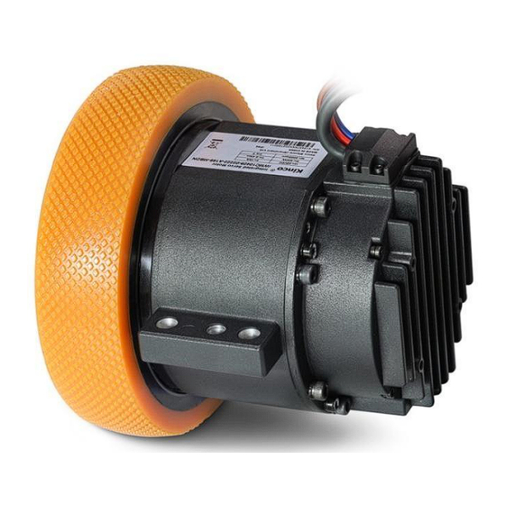
Preface iWMC integrated servo wheel is a fully integrated design power module released by Kinco. The integration of the wheel, reduction drive, servo motor and driver modules into a single package optimises the wheel structure, simplify the installation process and shortens the whole wheel installation time. This product is available in two power options and are Ideally suited for the travel axis of mobile robots with loads of 600 kg and 800kgs. -
Page 4: Cautions
iWMC Integrated Servo Wheel User Manual Cautions Please read and follow the requirements in this manual carefully as it will help you set up and operate the drive correctly and to optimize its performance. Please be aware of the contents of the warning and strictly follow the requirements, otherwise dangerous situations may occur. -
Page 5: Table Of Contents
iWMC Integrated Servo Wheel User Manual Table of Contents PREFACE………………….........................1 Cautions ..........................1 Chapter1 Model Description & Installation ................. 1 Product Introduction and Nameplate Description ............1 1.1.1 iWMC Integrated Servo Wheel Models ................1 1.2 iWMC Integrated Servo Wheel Installation & Precautions ............. 2 1.2.1 Installation Dimension .................... - Page 6 iWMC Integrated Servo Wheel User Manual 3.4 Read/Write Drive Configuration .................... 12 3.4.1 Read Driver Configuration .................... 12 3.4.2 Write Settings to The Drive ................... 13 3.5 Velocity Mode Introduction ....................15 3.6 Digital I/O Functions ......................16 3.6.1 Digital Input ........................16 3.6.2 Digital Output ........................
-
Page 7: Chapter1 Model Description & Installation
180mm diameter rubber covered wheel, standard extension cable connector 800KG Load Rating With reduction drive, with brake, without 180mm iWMC10415-05417-0000-MBDT diameter rubber covered wheel, standard extension cable connector Motion Control Products Ltd. Tel.: +44 (0)1202 599922 www.motioncontrolproducts.com Page | 1... -
Page 8: Iwmc Integrated Servo Wheel Installation & Precautions
Diagram 1-1 iWMC Integrated servo wheel motor model and nameplate information iWMC Integrated Servo Wheel Installation & Precautions Drive parameters Minimum Normal value Maximum Input voltage Brake Voltage — — Motion Control Products Ltd. Tel.: +44 (0)1202 599922 www.motioncontrolproducts.com Page | 2... -
Page 9: Installation Dimension
This product should only be operated by electrical engineers who are familiar with the following regulations: —Installation and operation of electrical control systems —Applicable regulations for operating safety engineering systems —Applicable provisions for accident protection and occupational safety —Document for the product Motion Control Products Ltd. Tel.: +44 (0)1202 599922 www.motioncontrolproducts.com Page | 3... -
Page 10: Electrical Requirements
The rated working altitude is below 1000 meters, and when the working altitude Height is above 1000 meters, every 100 meters of rise needs to be reduced by 1.5%. The maximum working altitude is 4000 meters. Motion Control Products Ltd. Tel.: +44 (0)1202 599922 www.motioncontrolproducts.com Page | 4... -
Page 11: Chapter2 System Interfaces And Wiring
Brake resistor model [Ω] [VDC] T-10R-100 Table 2-2 Fuse reference specifications Model Drive power (W) Fuse specifications iWMC10409 integrated servo wheel 20A/58VDC iWMC10415 integrated servo wheel 1050 90A/58VDC Motion Control Products Ltd. Tel.: +44 (0)1202 599922 www.motioncontrolproducts.com Page | 5... -
Page 12: Interface Definition
White/ Red High level: Input voltage 12.5VDC - 30VDC Input current 4-20mA White / Orange Low level: 0VDC - VDC Input frequency: <1KHz COMI White / Brown Input common Motion Control Products Ltd. Tel.: +44 (0)1202 599922 www.motioncontrolproducts.com Page | 6... -
Page 13: Power Supply Port
Diagram 2-5 Recommended circuit wiring diagram for forced releasing the brake 2.2.2 Power Supply Port Pin No. Name Pin Function Drive power supply input must be connected. Input voltage: 24~60VDC Motion Control Products Ltd. Tel.: +44 (0)1202 599922 www.motioncontrolproducts.com Page | 7... -
Page 14: Brake Resistor Port
C6350HM-2P-V0 (milky white) C6350HF-2P-V0 (milky white) Pins: SHANGYI C6350M-TBe (Male) Pins: SHANGYI C6350F-TBe (Female) Cable Specifications: Wiring Specifications Power cord 16AWG Communication, I/O, etc 28AWG Brake resistance 16AWG Motion Control Products Ltd. Tel.: +44 (0)1202 599922 www.motioncontrolproducts.com Page | 8... -
Page 15: Chapter 3 Kincoservo+ Software Introduction
Save a project via menu item File->Save, or by clicking the button and saving as a .kpjt file. Note Saving the project only saves the window in the computer software, and cannot save the parameters in the drive. Motion Control Products Ltd. Tel.: +44 (0)1202 599922 www.motioncontrolproducts.com Page | 9... -
Page 16: Start Communication
RS485 communication port (RS485 protocol defaults to RS232 communication protocol) to connect with the computer. RS485 communication terminal definition refer 2.2.1 for details. ⚫ Node ID and baud rate setting are not activated until after saving and rebooting. Motion Control Products Ltd. Tel.: +44 (0)1202 599922 www.motioncontrolproducts.com Page | 10... -
Page 17: Object (Add, Delete, Help)
Click Help to read a description of the selected object in the Object Dictionary. Initialise, Save And Reboot Click Driver->Initialize/Save. The following window appears: Figure 3–4 Initialise, save, reboot Click the corresponding item to finish the necessary operation. Motion Control Products Ltd. Tel.: +44 (0)1202 599922 www.motioncontrolproducts.com Page | 11... -
Page 18: Load Firmware
3.4.1 Read Driver Configuration Click on the menu bar "Tools" -> "R/W Diver Configuration" - > "Read Settings from Driver", or click the button , the following window appears: Motion Control Products Ltd. Tel.: +44 (0)1202 599922 www.motioncontrolproducts.com Page | 12... -
Page 19: Write Settings To The Drive
3.4.2 Write Settings to The Drive button , the following Click the menu bar“Tools”->“R/W Diver Configuration”->“Write Settings to Driver”, or click window appears: Motion Control Products Ltd. Tel.: +44 (0)1202 599922 www.motioncontrolproducts.com Page | 13... - Page 20 .cdi file. ⚫ Disconnect the 485/CAN/EtherCAT bus and disable the drive before writing settings to the drive, as this may prevent some objects from being written successfully. Motion Control Products Ltd. Tel.: +44 (0)1202 599922 www.motioncontrolproducts.com Page | 14...
-
Page 21: Velocity Mode Introduction
Mode 3 takes effect Default 100rps/s In the "Basic Operation" window of the computer software, we can find these parameters and set them respectively, in sections 6, 7, 10, 11 Motion Control Products Ltd. Tel.: +44 (0)1202 599922 www.motioncontrolproducts.com Page | 15... -
Page 22: Digital I/O Functions
Internal: This is the result of Simulate, Real and Polarity via the logic formula;means “active”, logic status of the selected function is 1; means “inactive”, logic status of the selected function is 0. Motion Control Products Ltd. Tel.: +44 (0)1202 599922 www.motioncontrolproducts.com... -
Page 23: Digital Output
Real: Shows the real digital input hardware status. This is the result of Simulate, Polarity and Logic State, means that digital input is ON, means that digital input is OFF. Motion Control Products Ltd. Tel.: +44 (0)1202 599922 www.motioncontrolproducts.com Page | 17... -
Page 24: Scope
During operation, if the equipment does not perform as expected, or other unexpected occurs, an oscilloscope can be used to analyse the problem. Click to open the scope window. Motion Control Products Ltd. Tel.: +44 (0)1202 599922 www.motioncontrolproducts.com Page | 18... - Page 25 Moving cursor: Hold down the left mouse button, drag the cursor to move, the sampled data, the difference between X1X2 and Y1Y2 will be displayed in the following area: Copy: Copy the sampled data to the pasteboard, you can open Excel to paste the data directly Motion Control Products Ltd. Tel.: +44 (0)1202 599922 www.motioncontrolproducts.com...
-
Page 26: Error Display And Error History
Error History: Click menu item“Driver”->“Error History”, the History Error window will pop up and display the last 8 error messages, including error word, bus voltage, speed, current, temperature, operating mode, power tube status. The most recent historical faults are displayed in the first row. Motion Control Products Ltd. Tel.: +44 (0)1202 599922 www.motioncontrolproducts.com... - Page 27 Pulse input frequency too high Motor Temperature 0x4310 Motor temperature sensor alarm No encoder connected or no encoder Encoder information 0x7331 communication reply EEPROM data 0x6310 EEPROM checksum fault Motion Control Products Ltd. Tel.: +44 (0)1202 599922 www.motioncontrolproducts.com Page | 21...
- Page 28 0x6321 connected The current sampling ADC reaches its limit and the The ADC samples saturated 0x2321 current runs out of control Service timeout 0x81FF Communication bus error extension Motion Control Products Ltd. Tel.: +44 (0)1202 599922 www.motioncontrolproducts.com Page | 22...
-
Page 29: Chapter4 Performance Tuning
This data is 1/32 of KVI and is mainly used for setting up 60F90710 Kvi/32 0-32767 high-resolution encoders 60F90508 Speed_Fb_N Speed feedback filtering for velocity loops 0~45 Motion Control Products Ltd. Tel.: +44 (0)1202 599922 www.motioncontrolproducts.com Page | 23... - Page 30 Normally, if the machine is stiff and light, we can use the 1st feedback filter or disable the feedback filter. If the machine is soft and heavy, we can use the 2nd order filter. Motion Control Products Ltd. Tel.: +44 (0)1202 599922 www.motioncontrolproducts.com...
- Page 31 Normally the default value is fine. This parameter should be added if the application system has a big extend force, or should be reduced if the output current is easily saturation and the saturation output current will cause some low frequency oscillation. Motion Control Products Ltd. Tel.: +44 (0)1202 599922 www.motioncontrolproducts.com...
-
Page 32: Tuning Position Loop
In fact this function will expend part of the velocity loop response ability, so if the setting can’t match the position loop proportional gain and the velocity loop bandwidth, the overshot will happen. Motion Control Products Ltd. Tel.: +44 (0)1202 599922 www.motioncontrolproducts.com... - Page 33 Normally, if the machine system oscillates when it starts and stops, a larger Pos_Filter_N is suggested. Step5: Notch filter The notch filter can suppress resonance by reducing gain around the resonant frequency. Antiresonant frequency=Notch_N*10+100 Motion Control Products Ltd. Tel.: +44 (0)1202 599922 www.motioncontrolproducts.com Page | 27...
-
Page 34: Other Factors That Affect Performance
– all of these can influence final control performance. Control performance affects the machine’s final performance, as well as precision, responsiveness and stability. Motion Control Products Ltd. Tel.: +44 (0)1202 599922 www.motioncontrolproducts.com... -
Page 35: Chapter 5 Alarm Exclusion
1.Add fan, improve the cooling environment controller’s power module of the controller. The drive temperature is has reached the alarm value 2.Add drive installment distance 001.0 4210 too high 3.Vertically install drive Motion Control Products Ltd. Tel.: +44 (0)1202 599922 www.motioncontrolproducts.com Page | 29... - Page 36 1. Check if power supply output power can 18V, power supply voltage is 040.0 5122 Low logic voltage meet with requirements 2. Change power supply with bigger power pulled down Motion Control Products Ltd. Tel.: +44 (0)1202 599922 www.motioncontrolproducts.com Page | 30...
- Page 37 2. Click “Init Control Parameters”-> “Save power is turned on and 800.0 6310 EEPROM Data errors Control Parameters”-> “Save data is read from the 3. Motor Parameters”->“Reboot” Import cdi file EEPROM by software Motion Control Products Ltd. Tel.: +44 (0)1202 599922 www.motioncontrolproducts.com Page | 31...
- Page 38 Change the encoder counting direction motor and position encoder The primary encoder Master encoder counting Ensure that the ground connection and the 800.0 0x7306 count is incorrect error encoder shield work well. Motion Control Products Ltd. Tel.: +44 (0)1202 599922 www.motioncontrolproducts.com Page | 32...
-
Page 39: Chapter 6 Rs485 Communication
1: Use RS232 protocol protocol selection Note: It needs to be set to 0, save and restart. 65100E10 RS485 mode Data = 8, stop = 1, no parity Fixed value Motion Control Products Ltd. Tel.: +44 (0)1202 599922 www.motioncontrolproducts.com Page | 33... -
Page 40: Modbus Rtu Communication
CR C High High High code address data-in byte byte byte byte byte byte 1 byte 2 bytes 1 byte 1 byte 2 bytes byte byte byte byte byte Motion Control Products Ltd. Tel.: +44 (0)1202 599922 www.motioncontrolproducts.com Page | 34... -
Page 41: Modbus Message Example
01106F 0000 020455 5500 081A 47 3100 Controlword Enable F 010631 0000 0FC7 32 3200 Status word Read register status 01 03 32 00 00 02 CA B3 Motion Control Products Ltd. Tel.: +44 (0)1202 599922 www.motioncontrolproducts.com Page | 35... - Page 42 Operation_Mode 010635 0000 03C6 07 60FF0020 Target_Speed 150RPM 01106F 0000 020455 5500 081A 47 60400010 Controlword 010631 0000 0FC7 32 60830020 Profile_Acc 610.352rps/s Default 60840020 Profile_Dec 610.352rps/s Default Motion Control Products Ltd. Tel.: +44 (0)1202 599922 www.motioncontrolproducts.com Page | 36...
-
Page 43: Chapter7 Canopen Communication
S (save): The object can be stored in Flash-ROM without lost after power failure. CANOpen Bus Communication Hardware Table 7-2 Pin name and function description table Terminals Pin number Signal identification Signal name CAN_H CAN in CAN_L CAN_H CAN out CAN_L Motion Control Products Ltd. Tel.: +44 (0)1202 599922 www.motioncontrolproducts.com Page | 37... - Page 44 The servo wheel does not need to be connected to an external 24V power supply to supply power to CAN. Table 7-4 The max. distance at different baud rate are shown in following table (Theory) Communication speed (bit/s) Communication distance (M) 800K 500K 250K 125K 1000 Motion Control Products Ltd. Tel.: +44 (0)1202 599922 www.motioncontrolproducts.com Page | 38...
-
Page 45: Canopen Bus Communication Software
Initiate Domain Download protocol; The SDO command word (first byte of the SDO CAN message) syntax of the protocol is described in Tables 10-8 and 10-9, where "-" indicates irrelevance and should be 0) . Motion Control Products Ltd. Tel.: +44 (0)1202 599922 www.motioncontrolproducts.com... - Page 46 Table 7-8 Receive SDO message when read parameters Daten Identifier Receive Object Object Max 4 bytes 0x580+Node_ID command index subindex data Note: When SDO message are sent, commands are 0x40; Motion Control Products Ltd. Tel.: +44 (0)1202 599922 www.motioncontrolproducts.com Page | 40...
- Page 47 The data types do not match, and the service parameter lengths do not match 0x06070012 The data types do not match, and the service parameter length is too large Motion Control Products Ltd. Tel.: +44 (0)1202 599922 www.motioncontrolproducts.com Page | 41...
- Page 48 The default ID allocation table is based on the CAN-ID (11 bits) defined in CANOpen 2.0A (The COB-ID of CANOpen 2.0B protocol is 27 bits), include function code (4 bits) and Node-ID (7 bits) as shown in Diagram7-12. Motion Control Products Ltd. Tel.: +44 (0)1202 599922 www.motioncontrolproducts.com...
- Page 49 501H-57FH 1403H SDO (Send/Server) 1011 581H-5FFH 1200H SDO (Receive/Client) 1100 601H-67FH 1200H NMT Error Control 1110 701H-77FH 1016H-1017H Note: 1. The smaller the COB-ID, the higher the priority; Motion Control Products Ltd. Tel.: +44 (0)1202 599922 www.motioncontrolproducts.com Page | 43...
- Page 50 In interpolation mode, the driver receives data first after detecting an RPDO signal, but only updates the object data at a specific point in time. Motion Control Products Ltd. Tel.: +44 (0)1202 599922 www.motioncontrolproducts.com...
- Page 51 Byte 0 0x700+Master station ID Master station state Case messages (Master station ID=127): 77F 05 Table7-16 State value meaning State value Meaning 0x00 Boot-up 0x04 Stopped 0x05 Operational Motion Control Products Ltd. Tel.: +44 (0)1202 599922 www.motioncontrolproducts.com Page | 45...
- Page 52 Standard CAN slaves generally support only one node protection method, FD5 series servo drives support both protection methods. However, a node cannot support both node protection and heartbeat packets, so only one of them can be selected as protection. Motion Control Products Ltd. Tel.: +44 (0)1202 599922 www.motioncontrolproducts.com...
- Page 53 Table 7-20 Value table Command NMT service 0x01 Open node 0x02 Close node 0x80 Come to pre-operation status 0x81 Reset node 0x82 Reset communication Description of the emergency message Motion Control Products Ltd. Tel.: +44 (0)1202 599922 www.motioncontrolproducts.com Page | 47...
- Page 54 The motor temperature is too high 0x4310 0x7382 failure The communication encoder did The primary encoder 0x7331 0x7306 not respond count is incorrect EEPROM data error 0x6310 Table7-23 Error register Motion Control Products Ltd. Tel.: +44 (0)1202 599922 www.motioncontrolproducts.com Page | 48...
-
Page 55: Canopen Bus Communication Settings
500k 2F810008 CAN baud rate 250k 125k Note: You need to save and then restart. CAN communication interrupt mode Communication 60070010 0: Not processed interruption mode 1: Error Motion Control Products Ltd. Tel.: +44 (0)1202 599922 www.motioncontrolproducts.com Page | 49... - Page 56 The heartbeat packet data of the slave station is not saved when power down, and is configured by the master station on power-on, and it should be noted that the data format is HEX Motion Control Products Ltd. Tel.: +44 (0)1202 599922 www.motioncontrolproducts.com Page | 50...
Need help?
Do you have a question about the iWMC Series and is the answer not in the manual?
Questions and answers