Table of Contents

Subscribe to Our Youtube Channel
Related Manuals for comarme GEM F470


Summary of Contents for comarme GEM F470
- Page 1 GEM F470-470S-520-670 USE AND MAINTENANCE MANUAL Code MANT-10063-02 COMARME S.r.l. Quartiere Mirabella snc 20081 Abbiategrasso (MI) ITALY Tel. +39 02 9422002 Fax. +39 02 9422096 Web: www.comarmesrl.com E-mail: info@comarmesrl.it Rev. - 13.05.2022...
-
Page 2: Table Of Contents
Recommended spare parts ..................................56 5.12 Intervention record sheet .................................... 57 PUTTING OUT OF SERVICE AND DISMANTLING ..........................58 Temporary putting out of service ................................. 58 Dismantling ........................................58 ANNEXES ........................................59 A01 - WIRING DIAGRAM A02 - SPARE PARTS LIST 2/59 GEM F470-470S-520-670... -
Page 3: Declaration Of Conformity
3/59 GEM F470-470S-520-670... -
Page 4: Use Of The Manual
The operations whose execution requires qualified or specialized staff, in order to avoid any danger, are indicated with this symbol. It is advisable to train the staff in charge of the machine and to check that what is envisaged is under- stood and carried out. 4/59 GEM F470-470S-520-670... -
Page 5: Informative Letter
The descriptions and the pictures it contains are not to be considered as binding. Although the main features of the machine described in this manual are not subject to change, COMARME S.r.l. reserves the right to change any part, detail and accessory it deems necessary to improve the machine or for manufacturing or commercial requirements, at any time and without being obliged to update this manual immediately. - Page 6 The original configuration of machine must not be changed at all. On receiving the machine make sure the supply corresponds to what has been ordered. In case of non conformity please inform COMARME S.r.l. immediately. Also make sure that the machine has not been damaged during transport.
-
Page 7: Transport And Handling
The head of the department must always follow all the standards and the legal provisions concerning accidents and safety at work, that are in force nationally, locally and in business. Some areas where to deposit materials must be identified. 7/59 GEM F470-470S-520-670... -
Page 8: Transport
Any options ordered with the machine rest on additional pallets. Storage During transport and storage make sure the temperature is between -5 and 40° C. If the machine is stored, make sure the relative humidity is between 30% and 95%. 8/59 GEM F470-470S-520-670... -
Page 9: Unpacking
Place the forks on the long side of the machine so that it rests on the supporting structure. Then rest the machine on the ground. WARNING Dispose of the packages properly delivering them to associations in charge of their elimination and recycling. A - Use and maintenance manual with EC declaration of conformity. B - Toolbox. 9/59 GEM F470-470S-520-670... -
Page 10: Handling
A fork lift truck can be used to handle the machine through the departments (see picture 5). Put the forks below the machine structure and remove it from the lower base pallet. WARNING During the handling always move very slowly. This operation must be assisted by an operator in charge of signalling. 10/59 GEM F470-470S-520-670... -
Page 11: Description Of The Machine
Air pressure Air consumption cycle Peso Weight W:\Vari\Loghi aziendali\COMARME\Logo COMARME [2428x372 PNG].png C O M A R M E S . r . l. Via Torrianese, 58 47824 Poggio Torriana (RN) - ITALY M A D E I N I T A L Y... -
Page 12: Description Of The Machine
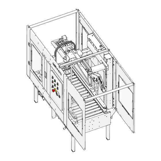
The only areas without guards are the box inlet and outlet. After positioning the machine in the production line the user must eliminate any risk in the box inlet and outlet area according to the features of the handling line. 12/59 GEM F470-470S-520-670... - Page 13 Knob for adjusting the drive belt width Knob for adjusting the taping head holding carriage height Control panel Air regulation unit Taping machine inspection door Box outlet area Upper taping head Lower taping head Flap closing device Flap closing device inspection door 13/59 GEM F470-470S-520-670...
-
Page 14: Technical Features
Technical features The table below shows the main technical features of the machine. Technical features Technical features GEM F470-470S-520-670 Machine weight 293 Kg Weight with packaging 646 Lb Power installed 805 Lb Box transfer speed about. 72 feet. Max. allowable pressure... - Page 15 GEM F470-470S-520-670 Technical features Technical features Motor protection IP54 Min. + 5°C / 41° F Service temperature Max. +35 °C / 95° F The equivalent continuous (A) weighted sound pressure level in the work- 78 dB (A) station is equal to Max.
-
Page 16: Dimensions
Dimensions The machine measures are indicated below in mm. 16/59 GEM F470-470S-520-670... -
Page 17: Field Of Application
COMARME S.r.l. declines all responsibility in case of accidents due to the use of the machines by UNAU- THORIZED and unqualified staff, or who use them for purposes different from the above-mentioned ones, WITHOUT THE WRITTEN AUTHORIZATION OF THE MANUFACTURER AND THE ADAPTATION OF THE TECHNI- CAL FEATURES. - Page 18 The side flaps can be opened outwards from 0° to max. 10°. The side flaps MUST not be bent inwards. The front and rear flaps can be opened outwards up to 10° while their inward inclination is not important (see picture 9). max 10° max 10° 18/59 GEM F470-470S-520-670...
-
Page 19: Installation
Do not install the machine without the suitable protections. WARNING COMARME S.r.l. machines are NOT conceived for working in places at risk of explosion and/or at high risk of fire. The machine installation in a plant requires special precautions: areas equipped with precise energy sources to feed the plant, some specialized and qualified staff to carry out this work and with the necessary equipment to position and install the machine. - Page 20 OBLIGATIONS OF THE CUSTOMER: COMARME S.r.l. declines all responsibility for damage to people, objects or animals due to the failure to in- stall protection systems or to their disassembly. The manufacturer is not to be held responsible if the plant user does not follow the instructions below.
-
Page 21: Free Spaces
(see picture 11). We recommend checking the suitability to carry loads near the supports. WARNING WARRANTY AND RESPONSIBILITY DECAY IN CASE the machine is not installed ac- cording to the indications provided for by the manufacturer. 21/59 GEM F470-470S-520-670... -
Page 22: Component Assembly
- pull out legs "B" to the required length (max. 100 mm) and tighten screws "A" . Make sure that at the end of these operations the machine is on a level in both directions, lengthwise and crosswise (see picture 13). 22/59 GEM F470-470S-520-670... - Page 23 The machine can be connected mechanically with other elements of the line (ex. box spacing units, roller ta- bles, etc.). For the mechanical connection use the proper connection kit (see picture 14). For the 375x500mm roller table extension with connecting brackets, see picture 15. 23/59 GEM F470-470S-520-670...
- Page 24 After setting up the taping head, insert it into the suitable compartment of the roller table, making sure that the supporting pins "A" (see picture 16) are correctly inserted into the slots "B" on the frame (see picture 17) and that the direction is as indicated in picture 16. 24/59 GEM F470-470S-520-670...
- Page 25 "B" by sliding them towards the outside of the machine as shown in picture 19; tighten the nuts "A". • To place the lower taping head T32-T33 proceed as follows: remove the supports "B"; refit the supports using the square holes "C"; tighten the nut "A". 25/59 GEM F470-470S-520-670...
- Page 26 "B" (see picture 21) as far as they will go into the grooves "C" (see picture 20). Then lock the taping head by lowering the proper level "A" (see picture 20). WARNING Depending on the taping head model used, position the appropriate supports "D" (see picture20) as shown on page 27. 26/59 GEM F470-470S-520-670...
- Page 27 • To place the upper taping head T32-T33 proceed as follows: remove the supports "A"; place the taping head using the appropriate slots in the unit holding supports (see picture 23); refit the supports "A" using the square holes "D" in the bracket. 27/59 GEM F470-470S-520-670...
-
Page 28: Electrical Connection
First of all make sure the lines can feed the whole plant correctly, in compliance with the safety standards in force (for the required features see paragraph 2.3). Before connecting the machine to the mains, make sure the main switch "A" (see picture 26) is on OFF and no object is on the working surface. 28/59 GEM F470-470S-520-670... - Page 29 Air pressure Air consumption cycle Peso Weight W:\Vari\Loghi aziendali\COMARME\Logo COMARME [2428x372 PNG].png C O M A R M E S . r . l. Via Torrianese, 58 47824 Poggio Torriana (RN) - ITALY M A D E I N I T A L Y •...
- Page 30 • Start the machine by pressing the main switch. • Check for the correct rotational direction of the drive belts as indicated by the arrow in picture 28. If the rotational direction should be reversed, invert the two phase wire connectors on the plug. § 30/59 GEM F470-470S-520-670...
-
Page 31: Pneumatic Connection
Check the air pressure using the "5" pressure gauge. Adjust the pressure between 5 and 6 bar based on the rigidity of the boxes to be taped. For corrections, use the air delivery knob on the FR unit, turning clockwise to increase or anti-clockwise to decrease. 31/59 GEM F470-470S-520-670... -
Page 32: Relief Photocell Positioning
This photocell detects the presence of boxes in the taping machine outlet area, stopping the working cycle. Fix the photocell in a position allowing detecting correctly the pres- ence of any box on the passage surface of the outlet boxes. 32/59 GEM F470-470S-520-670... -
Page 33: Normal Use
Use the machine for purposes that are different from the ones described in this use and maintenance manual. Allow unauthorized personnel to operate on the machine. Clean the machine while it is running. 33/59 GEM F470-470S-520-670... - Page 34 The safety systems must be only used as “safety stop” devices and not as machine stop control device. WARNING Before starting the machine, all its protections must be closed. 34/59 GEM F470-470S-520-670...
-
Page 35: Operator Position
In standard configuration, the control panel is on the left side of the machine, as shown in picture 30. Posizione operatore / Position opérateur Lato comandi / emergenza Posición del operador Côté commandements / bouton d'urgence Panel de mando / emergencia Control / emergency side Operator position 35/59 GEM F470-470S-520-670... -
Page 36: Control Panel
Allows you to restore normal operating conditions Tape end or breaking selector Allows you to activate/deactivate the taping control Emergency button When pressed, it stops the machine working Main switch Allows you to switch on the machine 36/59 GEM F470-470S-520-670... -
Page 37: Rear Flap Closing Unit Adjustment
- Widen the side pressure rollers (pict.32 pos.4) loosening the suitable knobs (pict.32 pos.5). - Put the box on the roller table. - Turn manually the rear flap closing unit until the flap closing lever is in vertical position. 37/59 GEM F470-470S-520-670... - Page 38 This is a basic adjustment. When the first box passes, check the flap closing lever and if necessary anticipate or delay its low- ering, by moving again the control microswitch to- wards the box inlet or outlet. 38/59 GEM F470-470S-520-670...
-
Page 39: Upper Taping Head Adjustment
(with a slight pres- sure) with the side walls of the box to tape. WARNING An excessive closing force of the driving belts locks the machine and damages it, especially when the box is thick. 39/59 GEM F470-470S-520-670... -
Page 40: Side Pressure Roller Adjustment
In case the rear flap closing unit reposi- tions too slowly, causing interference with the machine inlet boxes, increase the speed by adjusting the discharge (pos.5 pict.38). To adjust the rear flap closing lever speed act on the regulator (pos.6 pict.38). 40/59 GEM F470-470S-520-670... -
Page 41: Adjustment Of The Carriage Pressure On The Box
At this point, acting on the spring adjusting nut, it will be possible to increase or decrease the pressure of the carriage when touching the box. Turn the adjusting nut (pos. 4 pict .39) clockwise to increase or counter-clockwise to decrease the pressure. 41/59 GEM F470-470S-520-670... -
Page 42: Adjustment Of The Floatation System Of The Upper Taping Head Holding Carriage (Optional)
To activate this device, proceed as follows: - Insert the floatation system using the appropriate selector; - Increase the pressure of the counterweight according to need, acting on the pressure regulator. WARNING Excessive pressure increase can cause carriage instability. 42/59 GEM F470-470S-520-670... -
Page 43: Start Up Procedure
3. Press the RESET button "C". 4. Press the START button "D" 5. Shade the box inlet photocell. 6. Check the correct direction of rotation of the driving belts "F". NOTE: if necessary, see the wiring diagram enclosed. 43/59 GEM F470-470S-520-670... -
Page 44: Working Cycle
During the passage of the first box, check the optimal adjustment conditions of the machine, in particular: • the position of the rear flap closing lever control micro-switch • the width of the drive belts • the position of the upper head. 44/59 GEM F470-470S-520-670... -
Page 45: Machine Signal And Stop Conditions
For each maintenance operation, always disconnect the machine power supply and its pneumatic feed. Never carry out maintenance work with the machine in emergency conditions. When the machine is in emergency conditions it always has a part of the electrical system which is live. 45/59 GEM F470-470S-520-670... -
Page 46: Residual Risks
At the end of the work, even after stopping the machine, some components such as the motors can keep high temperatures. Therefore, at the end of the operations, make sure that nobody touches these parts until the heat is dissipated below a temperature of about 40-50°C. 46/59 GEM F470-470S-520-670... -
Page 47: Wrong And Dangerous Uses
LAW (Local law on safety at work); DO NOT USE WATER. Staff members should be trained to deal with such accidents. The machine can NOT work in areas at high risk of fire. WARNING IN CASE OF FIRE TURN OFF IMMEDIATELY THE POWER SUPPLY 47/59 GEM F470-470S-520-670... -
Page 48: Maintenance
Do not wear rings, watches, chains, bracelets, etc. during maintenance operations. Always wear individual protective devices (gloves, goggles, safety shoes, etc.). Do not use naked flames, pointed instruments or pins for cleaning operations. Do not smoke. 48/59 GEM F470-470S-520-670... -
Page 49: Ordinary Cleaning
This allows keeping the machine in good working conditions. Some tape or cardboard residues can be left near the machine or near the roller conveyors. During the machine cleaning remove them. 49/59 GEM F470-470S-520-670... -
Page 50: General Rules For Maintenance
Condensate drain Drain any condensate in the accumulation filter located under the main pressure regulator (see position "A" in picture 44). 50/59 GEM F470-470S-520-670... -
Page 51: Driving Belt Replacement
"C" fixing the front pulley "D" so that the pulley can be moved inwards, replace belt "E", insert a screwdriver into the suitable housing "F" by levering it so as to tighten the belt (see picture 46), tighten nut "C". 51/59 GEM F470-470S-520-670... - Page 52 "B" back on and lock it with screws "A" (see the previous page). WARNING This operation should be performed by specialized mechanical maintenance technicians. In any case, it is advisable to replace the belts at least once a year. 52/59 GEM F470-470S-520-670...
-
Page 53: Lubrication
49): loosen screws "B" and remove the protective guards "C" on the belts, loosen stop nut "D" on the front pulley "E" so that it may be moved towards the inside of the machine, remove belt "F", 53/59 GEM F470-470S-520-670... -
Page 54: Check Of The Drive Chain Tension
To replace the drive belt do as follows: loosen screws "A" and remove the belt guard "B", loosen locking nuts "D" and replace belt "C", re-adjust the belt tension by tightening locking nuts "D", reassemble guard "B". 54/59 GEM F470-470S-520-670... -
Page 55: Troubleshooting
• Check the locking valve operation The machine interrupts the auto- • Check the previous conditions and if necessary call the Technical Sup- matic cycle port System. In case of malfunction contact the Technical Service Centre (see par. "Informative letter"). 55/59 GEM F470-470S-520-670... -
Page 56: Recommended Spare Parts
5.11 Recommended spare parts GEM F470-470S-520-670 CODE Q.TY DESCRIPTION 851-01-913 Self-taping screw TBIC Ø3,9x9,5 801-10-527 Roller L=180,5mm 801-10-526 Roller=518mm 801-00-033 Knob 801-00-788 Spring for rear flap closing device 801-00-535 Tie rod 851-02-903 Limit switch PIZZATO art.FR538 851-04-042 Drive belt h=50x3370mm 851-03-879 Chain 3/8”x40 pitches closed... -
Page 57: Intervention Record Sheet
5.12 Intervention record sheet Fill in the table below with the features of the maintenance intervention carried out on the machine. DATE MACHINE PART OPERATION OPERATION TIME NOTES SIGNATURE 57/59 GEM F470-470S-520-670... -
Page 58: Putting Out Of Service And Dismantling
If the machine must be put out of service and dismantled, follow the standards to safeguard the environment as well as those on the recovery of recyclable materials. The parts to dismantle must be given to specialized companies with the regular authorization to transport and dispose of them. RECYCLE 58/59 GEM F470-470S-520-670... -
Page 59: Annexes
ANNEXES A01 - WIRING DIAGRAM A02 - SPARE PARTS LIST 59/59 GEM F470-470S-520-670... - Page 60 COMARME S.r.l. Quartiere Mirabella snc 20081 Abbiategrasso (MI) - ITALY Tel. +39 02 9422002 Fax. +39 02 9422096 Web: www.comarmesrl.com E-mail: info@comarmesrl.it...
Need help?
Do you have a question about the GEM F470 and is the answer not in the manual?
Questions and answers