Table of Contents

Related Manuals for comarme GEM XF520 BM


Summary of Contents for comarme GEM XF520 BM
- Page 1 GEM XF520 BM USE AND MAINTENANCE MANUAL Code MANT-10067-02 COMARME S.r.l. Quartiere Mirabella snc 20081 Abbiategrasso (MI) ITALY Tel. +39 02 9422002 Fax. +39 02 9422096 Web: www.comarmesrl.com E-mail: info@comarmesrl.it Rev. 0 - 13.07.2022...
-
Page 2: Table Of Contents
GENERAL INDEX DECLARATION OF CONFORMITY ................................ 3 USE OF THE MANUAL ..................................5 SYMBOLS USED ....................................5 INFORMATIVE LETTER ..................................6 TRANSPORT AND HANDLING............................8 Warnings for transport ................................8 Transport ....................................9 Storage ....................................9 Unpacking ....................................10 Handling ....................................11 DESCRIPTION OF THE MACHINE ............................12 Plate and labelling data ................................12 Description of the machine ..............................13... -
Page 5: Use Of The Manual
USE OF THE MANUAL The use and maintenance manual is the document accompanying the machine from its manufacture to its dismantling. Therefore it is an integral part of the machine itself. The manual must be read before starting ANY ACTIVITY involving the machine, including its handling. For a better consultation the instruction manual is divided into the following sections: Section 1 Transport, packing, handling and inspection on the purchased product. -
Page 6: Informative Letter
The descriptions and the pictures it contains are not to be considered as binding. Although the main features of the machine described in this manual are not subject to change, COMARME S.r.l. reserves the right to change any part, detail and accessory it deems necessary to improve the machine or for manufacturing or commercial requirements, at any time and without being obliged to update this manual immediately. - Page 7 On receiving the machine make sure the supply corresponds to what has been ordered. In case of non conformity please inform COMARME S.r.l. immediately. Also make sure that the machine has not been damaged during transport. GEM X520 BM...
-
Page 8: Transport And Handling
TRANSPORT AND HANDLING Warnings for transport The packagings are prepared according to the dimensions, the weight, the degree of protection required, the lifting safety. Thanks to the methods used, the packagings ensure stability and the fastening of the elements they contain. ALL THE MACHINE HANDLING OPERATIONS MUST BE CARRIED OUT ACCORDING TO THE FOLLOWING BASIC RULES: ... -
Page 9: Transport
1.2 Transport To transport the machine out of Italy, the machine itself is put into a barrier bag to ensure it is protected against bad weather. Then it is packed in a wooden case. To lift it use a fork lift truck. WARNING Before handling the machine and opening the package, follow the instructions on the package... -
Page 10: Unpacking
1.4 Unpacking If the machine is received in a wooden case, unpack it using a hammer with nail puller. Open the case starting from the upper covering then remove the side walls. WARNING Always protect your hands with gloves. Pay attention to any protruding nails (see picture 3). WARNING Follow the instructions on the packaging before handling and opening it. -
Page 11: Handling
1.5 Handling A fork lift truck can be used to handle the machine through the departments (see pictures 6 and 6a). Put the forks below the machine structure and remove it from the lower base pallet. WARNING During the handling always move very slowly. This oper- ation must be assisted by an operator in charge of sig- nalling. -
Page 12: Description Of The Machine
DESCRIPTION OF THE MACHINE Plate and labelling data The manufacturer identification plate in compliance with standards 2006/42/EC is applied on the machine. The plate must not be removed for any reason, even if the machine is resold. Always refer to the serial number (written on the plate itself) when contacting the manufacturer. The com- pany is not to be held responsible for damage to property or accidents to people, which might occur if the above-mentioned warnings are not observed. -
Page 13: Description Of The Machine
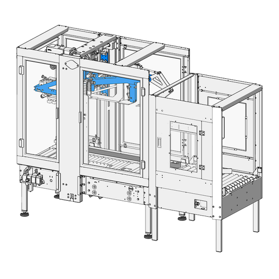
2.2 Description of the machine The machine described in this manual is an automatic machine for closing and upper sealing boxes with dif- ferent sizes using some adhesive tape. The machine closes automatically the four upper flaps of the boxes, of various sizes, dimensioning them according to the different types of inlet boxes automatically. - Page 14 Pos. Pos. Description Description Box inlet area Support legs Air regulation unit Electrical control panel with touchscreen panel Box outlet area Taping machine inspection window Upper taping head Side pressure devices Flap closing device Centring device 14/50 GEM X520 BM...
-
Page 15: Technical Features
2.3 Technical features The table below shows the main technical features of the machine. Technical features Technical features GEM XF520 BM GEM XF520 BM Machine weight 420 kg Weight with packaging 470 kg Power installed 3,2 kW Belt speed variable 25÷31 m/min. -
Page 16: Dimensions
Technical features Technical features GEM XF520 BM GEM XF520 BM Temperature of use Min. + 5°C / 41° F The equivalent continuous (A) weighted sound pressure level in the 78 dB (A) workstation is equal to Max. hourly production Note Production may vary according to 9 boxes / min. -
Page 17: Field Of Application
COMARME S.r.l. declines all responsibility in case of accidents due to the use of the machines by UNAUTHOR- IZED and unqualified staff, or who use them for purposes different from the above-mentioned ones, WITH- OUT THE WRITTEN AUTHORIZATION OF THE MANUFACTURER AND THE ADAPTATION OF THE TECHNICAL FEATURES. - Page 18 NOTE The machine can form boxes with the dimensions shown in the picture. WARNING To have a good functioning of the machine the proportion between length, height and weight of the box must be respected. In general, the length divided by height ratio must be equal to or greater than 0,6. In the event of particular dimensions, a check must be carried out with a sampling of boxes to be taped.
- Page 19 MACHINE WEIGHT Minimum: Even empty boxes with good quality cardboard can be taped. Maximum: approx. 6 kg for each 100 mm length of the box. An important feature of the boxes is that their weight, compared to the consistency of the cardboard, is such that the box travels straight on the roller conveyor and not inclined (see figure 9).
-
Page 20: Installation
Do not install the machine without the suitable protections. WARNING COMARME S.r.l. machines are NOT conceived for working in places at risk of explosion and/or at high risk of fire. The machine installation in a plant requires special precautions: areas equipped with precise energy sources to feed the plant, some specialized and qualified staff to carry out this work and with the necessary equip- ment to position and install the machine. - Page 21 OBLIGATIONS OF THE CUSTOMER: COMARME S.r.l. declines all responsibility for damage to people, objects or animals due to the failure to in- stall protection systems or to their disassembly. The manufacturer is not to be held responsible if the plant user does not follow the instructions below.
-
Page 22: Free Spaces
Free spaces To work freely on the machine and carry out the tooling or maintenance operations, it is necessary that there is sufficient passage along the two sides for the operator, at least 80 cm, as indicated in picture 11. WARNING We recommend leaving a suitable space to handle the boxes to be taped. -
Page 23: Component Assembly
Component assembly WORKING SURFACE HEIGHT ADJUSTMENT The machine is set up with the height of the roller table at 650 mm from the ground. This height can be increased from 600 mm up to 700 mm. WARNING To carry out this operation, insert the forks under the machine structure as indicated in par. - Page 24 UPPER TAPING HEAD POSITIONING After having prepared the taping head, insert the taping head in the special compartment, making sure that the orientation is that indicated in picture 18, sliding the four pins "A" (see picture 16) into the grooves "B" (see picture 15) as far as it will go, by pulling lever "C"...
- Page 25 • To place the upper taping head T21-T21,5-T22-T23 proceed as follows: unscrew the two levers "B" present in the front part of the unit holder structure and remove them; place the taping head using the special slots in the 4 spacers "A"...
-
Page 26: Electrical Connection
Electrical connection WARNING The machine electrical connection must be carried out only by qualified electricians, in compliance with the safety standards in force. WARNING Before carrying out any operation on the electrical equipment make sure that all the conductors, connecting parts and terminals are not energised. - Page 27 The machine is supplied WITHOUT power cable and socket. Each cable must be connected through connection terminals and must be signalled (see picture 24), and each wire it contains must be labelled so that its function is recognized. EVERY MACHINE MUST HAVE EARTHING and this must be adequately marked (see symbol below). All cables must pass through conduits;...
-
Page 28: Pneumatic Connection
Pneumatic connection In the lower part of the machine there is the connection for the feeding system. It is recommended to per- form the pneumatic connection with the system deactivated. Connect the machine's power supply fitting to the compressed air network by means of a quick coupling hose with an internal diameter of 8 mm and an external diameter of 10 mm. -
Page 29: Signal And Power Supply Connection
3.8 Signal and power supply connection Make the connections relating to the power supply and the various signals between the machine and the electrical panel through the special connectors provided. NOTE For further details refer to the wiring diagrams attached to this manual. GEM X520 BM 29/50... -
Page 30: Normal Use
NORMAL USE Introduction This section shows all the safety precautions to be followed for the proper use of the machine, as well as the operations to carry out during the first start up and during the normal use. Please read this section very carefully. Safety rules during use WHILE USING the machine the following precautions and safety criteria MUST BE STRICTLY... - Page 31 WARNINGS The person in charge of the facility and the operators who use the machine must follow all the standards and the legal provisions on accident prevention and safety at work. They must know the risks that can be found in the workplace and the emergency/safety plans arranged.
-
Page 32: Operator Position
Operator position The taping machine works automatically. The operator has the sole function of managing the work cycle from the panel on the control console. Picture 26 shows the area where the operator must be in order to operate on the control panel. The machine, in standard configuration, is provided with the control console positioned on the left side, as shown in picture 26. -
Page 33: Control Panel
Control panel The control panel, located on a control console, allows the operator to give instructions to the system. In detail, the control panel consists of: Pos. Pos. Description Description Function Function It allows setting and adjusting the functions of the Touchscreen panel machine* RESET push button... -
Page 34: Pneumatic Adjustments
Pneumatic adjustments SIDE BELT CLOSING FORCE PNEUMATIC ADJUSTMENT According to the rigidity of the boxes to be taped, adjust the air pressure to the side belts between 3 and 4 bar. For any corrections, use the air delivery knob "A" on the FR unit, turning it clockwise to increase or counter- clockwise to decrease the pressure (see picture 27). -
Page 35: Start-Up Procedure
Start-up procedure To start the machine, follow the procedure below (see picture 29): 1. Turn the main switch "A" to the ON position to power the elec- trical panel. 2. Check that the emergency button "B" is not pressed. 3. Press the RESET button "C". 4. -
Page 36: Working Cycle
Working cycle - Start the machine following the procedure indicated in the previous paragraph. - Once the box is filled, arrange it in the sealing direction (forward direction). - Insert the box into the machine manually or automatically. WARNING The boxes must arrive at the machine already properly centred and spaced. In the inlet area of the machine there is a centring and spacing device for boxes. -
Page 37: Machine Signal And Stop Conditions
4.8 Machine signal and stop conditions The machine has an indicator lamp (see pic. 30) with 3 colours to indicate its working status. Pos. Pos. Description Description machine stopped due to the end of the belt or in Red sector "A" on case of anomaly machine running with adhesive tape Yellow sector "B"... -
Page 38: Residual Risks
4.9 Residual risks Once the machine has been positioned inside the production line, the user must eliminate any risks present in the inlet and outlet area of the boxes, depending on the features of the handling line. At the end of the work, even after stopping the machine, some components such as the motors can keep high temperatures. -
Page 39: Maintenance
MAINTENANCE Maintenance A suitable maintenance is very important for a longer duration of the machine and it ensures safety from a functional point of view. We recommend making qualified and authorised staff carry out maintenance operations. The design and materials used reduce maintenance interventions to a minimum. The staff must be provided with the individual protection means that are usually used for similar operations, and they must follow the safety standards described in the following chapter. -
Page 40: Ordinary Cleaning
Ordinary cleaning The ordinary cleaning of the machine must be carried out every day in compliance with the specific quality procedure and with the machine disabled. This allows keeping the machine in good working conditions. Some tape or cardboard residues can be left near the machine or near the inlet and outlet roller conveyors. During the machine cleaning remove them. -
Page 41: General Rules For Maintenance
General rules for maintenance No special preventive maintenance operations are required. In any case, we recommend checking periodical- ly that the screws are perfectly tightened in order to achieve the best result at all times. Condensate drain Drain any condensate in the accumulation filter located under the main pressure regulator (see position "A"... -
Page 42: Driving Belt Replacement
Drive belt replacement The drive belts of the boxes are subject to wear (according to the number of working hours). To replace them, do as follows (see picture 33): loosen screws "A" and remove belt safety guards "B", loosen nut "C" fixing the front pulley "D" so that the pulley can be moved inwards, replace belt "E", insert a screwdriver into the suitable housing "F"... - Page 43 check the correct tension of the belt by pulling it out slightly about half way along the arm (see picture 35). The displacement of the belt from the guide should be about 20 mm. If this is not the case, adjust the tension by loosening nut "C", insert the screwdriver into the suitable housing "F"...
-
Page 44: Check Of The Drive Shaft Locking Screw Tightening
5.7 Check of the drive shaft locking screw tightening It is advisable to regularly check that the locking screw "A" on the drive shaft is tightened properly. To carry out this operation do as follows (see picture 36): loosen nut "A" fixing the front pulley "B" so that the pulley can be moved inwards, remove belt "C", insert the 38 mm wrench "D"... -
Page 45: Troubleshooting
Troubleshooting This chapter describes how to solve the most common problems which may arise in the machine. PROBLEM PROBLEM SOLUTION SOLUTION • Check the power supply presence • Check that the socket is plugged in • Check that the switch is enabled The machine does not start •... -
Page 46: Recommended Spare Parts
Recommended spare parts GEM XF520 BM CODE QTY. DESCRIPTION MECHANICAL PART CNN-56100-177 BLACK DRIVE BELT SV.3370X50 WITH CENTRAL GUIDE K9 MSNN-400117 SPLINED SHAFT D.25 DRIVING TRANSMISSION NAST-40333-01 BELT DRIVING PULLEY H=50 CNWN-300086 TOOTHED BELT P=3/8" Z=72 Art.360 H 100 CNE-13042-011 WORM SCREW REDUCT. - Page 47 GEM XF520 BM CODE QTY. DESCRIPTION PNEUMATIC PART ALTIVARATV320 SINGLE-PHASE COMPACT TRANSFORMERS 200-240V CNP-21012-020 0.37 KW 50/60 HZ WITH INTEGRATED EMC FILTER CNP-22023-012 PROFINET COMMUNICATION CARD 2 RJ45 CONNECTORS COMPACT COMMUNICATION CARD ADAPTER FOR ATV320 CNPN-200009 PNEU.CYLIND.DNCB-40-160-PPV-A CODE 532743 CNP-11106-020...
-
Page 48: Intervention Record Sheet
5.10 Intervention record sheet Fill in the table below with the features of the maintenance intervention carried out on the machine. DATE MACHINE PART OPERATION OPERATION TIME NOTES SIGNATURE 48/50 GEM X520 BM... -
Page 49: Putting Out Of Service And Dismantling
PUTTING OUT OF SERVICE 6.1 Temporary putting out of service If the machine is not to be used for more than 3 months, we recommend carrying out the following opera- tions: Disconnect the machine from the energy sources. Clean the machine. ... -
Page 50: Annexes
ANNEXES A01 - WIRING DIAGRAM A02 - SPARE PARTS LIST 50/50 GEM X520 BM... - Page 52 COMARME S.r.l. Quartiere Mirabella snc 20081 Abbiategrasso (MI) - ITALY Tel. +39 02 9422002 Fax. +39 02 9422096 Web: www.comarmesrl.com E-mail: info@comarmesrl.it...
Need help?
Do you have a question about the GEM XF520 BM and is the answer not in the manual?
Questions and answers