Table of Contents
Advertisement
Advertisement
Table of Contents

Related Manuals for Sunlover oasis IX9

Summary of Contents for Sunlover oasis IX9
- Page 2 Quick Reference Record your details here: Model No: Serial No: Purchase Date: Installer: Yes / No / 20 Warranty Registered Online: Date Registered Please record the information below during installation as this will be required for any service or warranty related work that may be required.
-
Page 3: Table Of Contents
Table of Contents Introduction Important Things to Note Specifications Quick Start Guide Safety Location of Installation and Airflow Clearance Air Deflector Installation Installation & Connection Controller Operation Troubleshooting Maintenance Technical Support Warranty Page 2 of 43... -
Page 4: Introduction
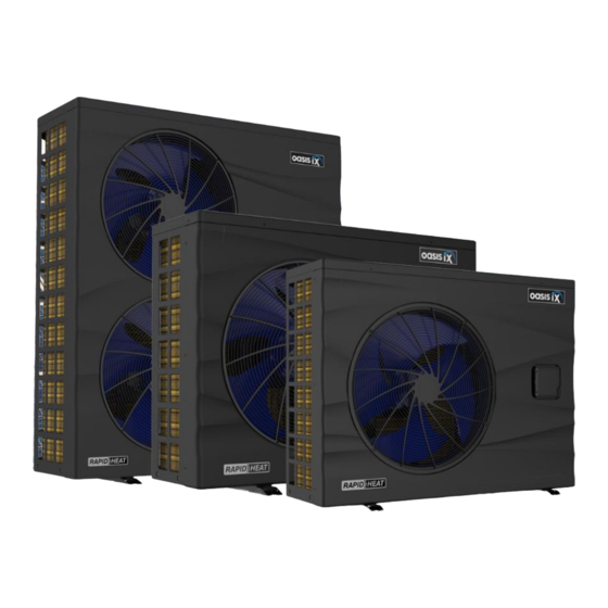
Introduction Congratulations on your recent purchase of your Oasis Heat Pump. Please take a moment to read through the entire manual before installing your new unit. There are 7 different size models in our range: This manual contains all the necessary information in regard to the installation, troubleshooting, Single Phase Three Phase... -
Page 5: Important Things To Note
Important Things to Note Check that you have received the package in good condition Ensure you meet the minimum clearances and recommended installation locations as outlined in the manual. Make sure that the unit is installed as per the ventilation diagrams to ensure efficient heating All accessories (drain barbs, rubber feet and barrel unions) and the installation manual is contained in a plastic bag inside the packaging of your heat pump Please refer to the warranty section of this manual and follow the outlined registration process... -
Page 6: Specifications
Specifications The data presented relates exclusively to the Oasis heat pump and excludes any auxiliary equipment. The product specifications mentioned above were precise at the time of printing, but are subject to change without prior notice. For the latest and most accurate information, please contact an Oasis heat pump specialist. iX13 iX19 iX24... - Page 7 Specifications Unit Dimensions Unit: mm iX9 / iX13 iX19 iX24 / iX28T iX28 / iX36T Page 6 of 43...
-
Page 8: Quick Start Guide
Quick Start Guide • Ensure you meet the minimum clearances and recommended installation locations as outlined in the manual. • All accessories (drain barbs, rubber feet and barrel unions) and the installation manual is contained in a plastic bag inside the packaging of your heat pump Pre-Installation Install the supplied rubber anti-vibration feet under the unit. - Page 9 Quick Start Guide Electrical Connection OASIS HEAT PUMPS MUST BE CONNECTED BY A LICENSED ELECTRICIAN IN ACCORDANCE WITH ALL RELEVANT AUSTRALIAN STANDARDS, APPLICABLE LAWS AND LOCAL LEGISLATIONS. Under no circumstances should an unlicensed person attempt to install or repair an Oasis heat pump themselves.
-
Page 10: Safety
Safety Installation, repair, or relocations should be completed by a fully qualified technician. If not carried out correctly, several hazards, such as fire, electric shock, water leakage, and injury, may occur. This appliance is not intended for use by persons (including children) with reduced physical sensory or mental capabilities, or lack of experience and knowledge, unless they have been given supervision or instruction concerning use of the appliance by a person responsible for their safety. -
Page 11: Location Of Installation And Airflow Clearance
Any space problem can be resolved easily with the optional purchase of a Sunlover Air Deflector to redirect the cold discharge air away, creating ample ventilation and airflow in any area. -
Page 12: Air Deflector Installation
Air Deflector Installation Sunlover offers Air Deflectors as an optional purchase. Recirculating the front air discharge back into the heat pump's air intake should be avoided. If there are space constraints, installing an Air Deflector is a straightforward and economical solution. -
Page 13: Installation & Connection
Installation & Connection Heater Condition Upon receiving the heater, inspect its packaging thoroughly for any apparent signs of damage and IMMEDIATELY notify your supplier if there are any signs of rough handling. NOTE: All accessories (drain barbs, rubber feet and barrel unions) and the installation manual is contained in a plastic bag inside the packaging of your heat pump. - Page 14 Installation & Connection First Time Operation When starting for the first time: • Ensure the water pump is adequately primed. • Adjust bypass valve to provide full flow to heat pump, which will aid in purging air from the system. •...
- Page 15 Installation & Connection Time Delay The unit is equipped with a 3-minute restart delay included to protect control circuit components and to eliminate short cycling. This time delay will automatically restart the unit approximately 3 minutes after each control circuit interruption.
- Page 16 Installation & Connection Electrical Connection Ensure the power cable and circuit protection device are of a suitable size for the heater being installed. Also check that there is adequate voltage and current available at the heater connection to run the unit. Voltage range should be 220-240 volts for single phase, and 380-415 volts for 3 phase units.
- Page 17 Installation & Connection PV Ready Integration For detailed information on the PV ready feature of the Oasis iX heat pump, we have a separate manual available for download. This manual specifically focuses on the installation, configuration, and operation of the PV ready functionality, allowing you to seamlessly integrate your heat pump with solar power systems.
-
Page 18: Controller Operation
Controller Operation Main Controller Interface The heat pump is equipped with a digital control panel with a touch screen, electronically connected and pre-set at the factory in heating mode. Compressor indicator Current time Normal Mode Mode selection key Fan indicator Silent Mode Auto/Heating/Cooling) Timer indicator... - Page 19 Controller Operation OFF Mode ON Mode When the heat pump is inactive (in standby mode) When the heat pump is active (running or setpoint the screen is black. OFF is displayed, as shown reached) screen blue. target below. temperature is displayed as shown below. To manually switch from OFF to ON mode and vice versa, press the ...
- Page 20 Controller Operation Adjusting the Target Set Temperature The setpoint can be changed in either ON or OFF mode in increments of 0.5°C. To change the desired pool temperature, swipe across to the right and touch the Temp Setting key. Adjust the temperature setting by swiping up and down and press OK to save. Press ...
- Page 21 Controller Operation Timer Settings - On / Off The heat pump is equipped with an on / off timer function, which allows users to choose specific start and finish times for the heat pump's operation to meet their specific requirements. ONE Start Timer and ONE Stop Timer option can be set for the heat pump's operation.
- Page 22 Controller Operation Tariff Timer Settings (Spot Timer) The heat pump is equipped with a Spot Time function, which allows users to customise up to six timer schedules to take advantage of time-of-use tariffs. This function can also be used to maximise self-consumption of PV solar energy where the heat pump is not connected to a compatible solar inverter or energy management system via the PV-Ready circuit(s).
- Page 23 Controller Operation Silent Mode Settings Silent mode forces the heat pump to operate in an economic and quiet manner. This feature is commonly used to reduce noise when running the heat pump overnight. When silent mode is active, the fan indicator icon on the home screen will change from [ ] to [ This function can be activated or deactivated manually, or by setting the silent timer.
- Page 24 Controller Operation Touchpad Lock The touchpad can be locked or unlocked in either ON or OFF mode. Lock activated Lock deactivated The touchpad lock can be activated from the home screen by touching and holding the key for five seconds.
- Page 25 Controller Operation Fault Indicator (continued) Error messages may occur for a number or reasons. Once resolved, the message is automatically stored and the fault indicator triangle disappears. If the heat pump will not operate and the fault indicator is continuously blinking, check the error message and consult with the troubleshooting table overleaf for possible causes.
-
Page 26: Troubleshooting
Troubleshooting Electronic Control Fault Message Table To assist in determining the cause of the error message, refer to the table below. Error Error Message Likely Cause Elimination Methods Code Inlet Temperature Sensor Fault The temperature sensor is open or short circuit Check or replace the temperature sensor Outlet Temperature Sensor Fault The temperature sensor is open or short circuit... - Page 27 Troubleshooting Electronic Control Fault Message Table (continued) Error Error Message Likely Cause Elimination Methods Code 1. Motor is in locked-rotor state 1. Replace the fan motor Fan Motor1 Fault F031 2. The wire connection between DC-fan motor 2. Check wire connections module and fan motor is not connected 1.
-
Page 28: Maintenance
During the service, they will check the operational pressures of the refrigeration system and clean the fin coil to ensure maximum performance. Do we have recommended service agents? Oasis and Sunlover Heating have a large database of recommended service agents. Please contact us for your local service agent details. Should I check my unit regularly? We recommend you check your unit regularly to avoid potential issues and damage to your heat pump. - Page 29 Maintenance CHECKS TO THE AREA Prior to beginning work on systems containing flammable refrigerants, safety checks are necessary to ensure that the risk of ignition is minimised. For repair to the refrigerating system, the following precautions shall be complied with prior to conducting work on the system. prolonged period of no usage.
- Page 30 Maintenance CHECKS TO THE REFRIGERATION EQUIPMENT Where electrical components are being changed, they shall be fit for the purpose and to the correct specification. At all times the manufacturer's maintenance and service guidelines shall be followed. If in doubt consult the manufacturer's technical department for assistance. The following checks shall be applied to installations using flammable refrigerants: •...
- Page 31 Maintenance REPAIRS TO SEALED COMPONENTS 1) During repairs to sealed components, all electrical supplies shall be disconnected from the equipment being worked upon prior to any removal of sealed covers, etc. If it is necessary to have an electrical supply to equipment during servicing, then a permanently operating form of leak detection shall be located at the most critical point to warn of a potentially hazardous situation.
- Page 32 Maintenance REMOVAL AND EVACUATION When breaking into the refrigerant circuit to make repairs or for any other purpose conventional procedures shall be used. However, it is important that best practice is followed since flammability is a consideration. The following procedure shall be adhered to: •...
- Page 33 Maintenance DECOMMISSIONING Before carrying out this procedure, it is essential that the technician is completely familiar with the equipment and all its detail. It is recommended good practice that all refrigerants are recovered safely. Prior to the task being carried out, an oil and refrigerant sample shall be taken in case analysis is required prior to re-use of reclaimed refrigerant.
-
Page 34: Technical Support
Technical Support and Warranty Requests For all warranty enquiries please contact your local distributor or contact Oasis directly and we will direct you to your nearest authorised repairer for assistance. • contact Oasis on 1800 815 913 or via our Service Request page on our web site;... -
Page 35: Warranty
(12) months only. Warranty Coverage During the Warranty Period, Sunlover warrants that the Product will be free from material defects in materials and workmanship under normal use and maintenance. This Warranty is subject to the terms and conditions set out hereunder. - Page 36 • No employee, agent or representative of Oasis or Sunlover Heating nor the Buyer has any authority to vary the terms this Warranty This warranty does not cover the following: a.
- Page 37 Warranty Owner’s Responsibility Proper operation and regular maintenance of the equipment are the responsibility of the owner, and should be carried out according to the recommended time and frequency specified in the manual to avoid voiding the warranty. The correction of any non-product fault or problem is not covered by this warranty.
- Page 38 Notes Page 37 of 43...
- Page 39 Notes Page 38 of 43...
- Page 40 Notes Page 39 of 43...
- Page 41 Notes Page 40 of 43...
- Page 42 Notes Page 41 of 43...
- Page 43 Notes Page 42 of 43...
- Page 44 Sunlover are the sole distributor of Oasis Heat Pumps in Australia For inquiries, contact us. sunloverheating.com.au sales@sunloverheating.com.au 1800 815 913 Head Office New South Wales Queensland New Zealand 6-8 Austral Place Unit 2, 10 Boden Road 11 Andy Court Oasis Heat Pumps...
Need help?
Do you have a question about the oasis IX9 and is the answer not in the manual?
Questions and answers