Table of Contents
Advertisement
Quick Links
Advertisement
Table of Contents

Related Manuals for Ronch RAPTOR DUTY R500MP


Summary of Contents for Ronch RAPTOR DUTY R500MP
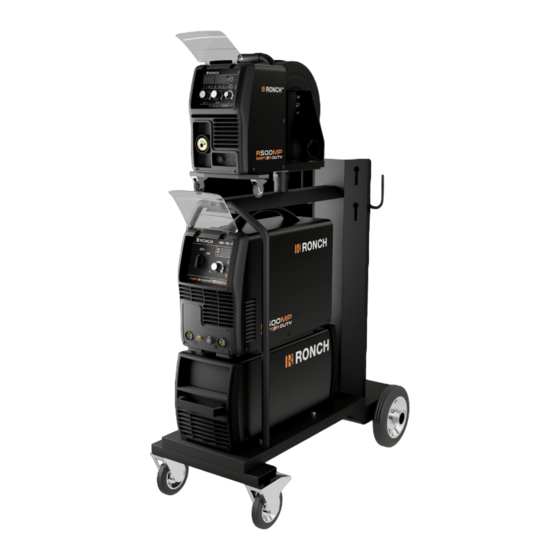
- Page 1 R500MP MULTIPROCESS...
-
Page 2: Table Of Contents
CONTENT 1. Safety • 1.1. Symbols Explanation • 1.2. Arc Welding warnings • 1.3. Knowledge of Electric and Magnetic Fields • 2. OVERVIEW • 2.1. Brief Introduction • 2.2. Working Principle • 2.3. Volt-Ampere Characteristic • 2.4. Volt-Ampere Characteristic • 3. - Page 3 4.6. Operation Notices • 5. MAINTENANCE & TROUBLESHOOTING • 5.1. Maintenance • 5.2. Troubleshooting • 5.3. Electrical schematic drawing •...
-
Page 4: Safety
1. Safety • 1.1. Symbols Explanation The above symbols mean warning! Notice! Running parts, getting an electric shock or making contacts with thermal parts will cause damage to your body and others. The underline message is as follows: Welding is quite a safe operation after taking several necessary protection measures! •... - Page 5 Never dip the electrode in water for cooling. Never simultaneously touch electrically “hot” parts of electrode holders connected to two welders because voltage between the two can be the total of the open circuit voltage of both welders. ...
- Page 6 DO NOT add any fuel near an open-flame welding arc or when the engine is running. Stop the engine and allow it to cool before refueling to prevent spilled fuel from vaporizing on contact with hot engine parts and igniting. Do not spill fuel when filling tank. If fuel is spilled, wipe it up and do not start engine until fumes have been eliminated.
-
Page 7: Knowledge Of Electric And Magnetic Fields
Never allow the electrode, electrode holder or any other electrically “hot” parts to touch a gas cylinder. Keep your head and face away from the cylinder valve outlet when opening the cylinder valve. Valve protection caps should always be in place and hand tight except when the cylinder is in use or connected for use. -
Page 8: Overview
2. Overview • 2.1. Brief Introduction MULTIMIG F SYN series of welding machines adopts the latest Pulse Width Modulation (PWM) technology and the Insulated Gate Bipolar Transistor (IGBT) power modules. It uses switching frequencies in the 20KHz-50KHz range so as to replace the traditional line-frequency transformer type welding machines. -
Page 9: Volt-Ampere Characteristic
diodes), and is outputted by inductance filtering. When MIG. Meanwhile, the welding current parameter can be adjusted continuously and infinitely to meet with the requirements of welding craft. • 2.3. Volt-Ampere Characteristic MULTIMIG F SYN series welding machine has an excellent volt-ampere characteristic, whose graph is shown as the following figure. - Page 10 • 2.4. Principles of welding...
-
Page 11: Parameters
3. Installation & Operation • 3.1. Parameters Models RAPTOR DUTY R500MP Parameters Input Voltage(V) 3~380/400/440±10% Frequency (HZ) 50/60 Input Current(A) MIG 43 TIG 32 MMA 43 Input Power(KW) MIG 23 TIG 18 MMA 23 Welding Current(A 40-500(MIG) ) Welding Voltage(V 10-50(MIG) )... -
Page 12: Equipment Connection
down with the fanrunning. When operating the machine again, the welding output current or the duty cycle should be reduced. • 3.3. Equipment Connection Operation Steps: 1. Connect the power cable of welding machine with the output switch in electric box on site. -
Page 13: Parts List For The Mig Gun
IFT0063 螺丝 M4X6 UNI 6107 • 3.4.2. Parts list for the MIG GUN IHJ0645 二氧化碳欧式后把套 ICG6000 导电嘴扳手 IHJ0028 电缆护套 12-16-25 MMQ IIC0500 带绝缘层送丝管0.6-0.8 3米 蓝色 ICN0663 同轴电缆组/16mmq/3米 IZT0071 送丝管锁紧螺母 IHJ0782 电缆支撑用球节 15AK ITB0059 欧式中央插头/弹性针 IHJ0715 手柄锁紧环 IHJ0063 焊枪锁紧螺母/塑料螺纹 IFT0874 螺丝 D.3x10 序号... -
Page 14: Wire Feeder
Pressure of the feed rolls remove metal dust from the filler wire’s surface which then find its way to the wire guide. If the wire guide is not cleaned, it gradually clogs up and causes wire feed malfunctions. Clean the wire guide in the following manner: Remove the welding gun’s gas nozzle, contact tip and contact tip’s adapter. - Page 15 NO. Parts Welding Voltage and other parameter regulator Welding Current and other parameter regulator Inductance regulator Manual wire key Air check key Water /Air selecting key 2T/4T welding mode selecting key Pre flow/Post flow/Soft start/Burn back selecting key MIG gun connector Spool gun connector Water connector Water connector...
- Page 16 The feed roller (No.16 in the picture) is factory set for welding filler wires of 0.8-1.0mm and 0.6mm diameter on the other side. The feed roller side must be changed if you use 0.6mm diameter filler wire. Threading the filler wire Threading the filler wire as the follow steps: Open the reel housing by pressing on the opening button and install the wire reel in such a way that it rotates counter clockwise.
-
Page 17: Operation
4. OPERATION • 4.1. Layout for the front and rear panel 1. Output cathode: When MIG mode, this polarity must connect the work piece. 2. Shield gas connector: Is connected to the gas input pipe of torch. 3. Aviation plug: TIG gun control connecter. 4. -
Page 18: Welding Operation
15. Welding current and other parameter display: Welding current and other parameter display when machine is working. 16. Choose welding method key: Pressing the key can choose four kinds material, MMA/MMA VRD/TIG/MIG. 17. Hot start LED: When the hot start LED is on, it can be altered on adjusting dial. 18. -
Page 19: Welding Parameters
• 4.3. Welding parameters Wire speed Welding current(A) Welding volt(V) φ0.8 φ0.9 φ1.0 φ1.2 φ1.6 3—4 3--4 2—4 15~17V 4—5 3--5 3—5 2--4 15~18V 120A 6—7 5--8 4—7 3--6 2--6 16~20V 160A 10—12 7--12 6--12 4--9 3--6 17~21V 200A 11--15 9--15 6--11 3--5 17~26V 250A... -
Page 20: Operation Environment
MULTIMIG 400F SYN MULTIMIG 500F SYN • 4.5. Operation environment Height above sea level ≤1000 M Operation temperature range -10~+40°C Air relative humidity is below 90 %( 20°C) Preferable site the machine some angles above the floor level, the maximum angle does not exceed 15℃. - Page 21 • 4.6. Operation Notices Read Section §1 carefully before starting to use this equipment. Connect the ground wire with the machine directly. Ensure that the input is three-phase: 50/60Hz, 380V ±15%. Before operation, none concerned people should not be around the working area and especially children.
- Page 22 5. Maintenance & Troubleshooting • 5.1. Maintenance In order to guarantee safe and proper operation of welding machines, they must be maintained regularly. Let customers understand the maintenance procedure of welding machines. Enable customers to carry on simple examination and inspections. Do your best to reduce the fault rate and repair times of welding machines to lengthen service life of arc welding machine.
- Page 23 Check the screws and bolts in the machine. If any is loose, please screw it tight. If it is shaved, please replace. If it is rusty, please erase rust on all bolts to ensure it works well. Quarter- Check whether the actual current accords with the displaying value. If they did not yearly accord, they should be regulated.
- Page 24 Wire reel Motor damaged Check and change it doesn’t Control circuit damaged Check the PCB work The press wheel is loosen or Press it tightly again weld wire skids Wire- feeder The wheel doesn’t fit with the Change the wheel doesn’t diameter of weld wire Wire reel...
- Page 25 • 5.3. Electrical schematic drawing...
- Page 26 R500MP MULTIPROCESS...
Need help?
Do you have a question about the RAPTOR DUTY R500MP and is the answer not in the manual?
Questions and answers