Motorola AP-PSBIAS-1P2-AFR - Power Injector Installation Guide
- Installation manual (2 pages)
Advertisement
To the Installer
This guide is intended for the technician responsible for installing the Power Injector. It assumes the technician is familiar with basic Ethernet LAN-based networking and device installation concepts. This guide provides specifications, procedures and guidelines to use during the installation process. This guide does not provide site-specific installation procedures. For detailed site-specific installation procedures, refer to the site-specific documentation derived from site survey and site network analysis.
Verifying Package Contents
Inspect the package contents and report any missing or damaged items to your sales representative. The packages should contain the following:
- Power Injector (pt # AP-PSBIAS-1P2-AFR)
- This Power Injector Installation Guide (72-99410-01)
Safety Information
Before operating any equipment, review this document for any hazards associated with installation and use of the device. Also, review standard practices for preventing accidents.
- Only trained and qualified personnel should install and remove the Power Injector.
- A power cord is not supplied with the device. Use only a correctly rated power cord that's certified, as appropriate, for the country of operation.
- The power cord must be a three-conductor type (two current carrying conductors and one ground conductor) terminated on one end by an IEC 60320 appliance coupler (for Power Injector connection) and on the other end by a plug containing a ground (earth) contact.
- The power cord must be rated for a minimum of 250VAC RMS operation, with a minimum rated current capcity of 5A [or a minimum wire gauge of 18AWG (0.75mm²)].
- The AC wall-socket outlet must be near the Power Injector and easily accessible.
- The Power Injector Data and Data & Power interfaces are qualified as SELV (Safety Extra-Low Voltage) circuits according to to IEC 60950. These interfaces can only be connected to SELV interfaces on other equipment.

- Read the installation instructions before connecting the Power Injector to a power source.
- Follow basic electricity safety measures whenever connecting the Power Injector to its power source.
- This product relies on on the building installation for short-circuit (over current) protection. Ensure a fuse or circuit breaker no larger than 120 VAC, 3A U.S. (240VAC, 1.5A international) is used on the phase conductor.
- A volatge mismatch can cause equipment damage and could pose a fire hazard. If the voltage indicated on the label is different from the power outlet voltage, do not connect the Power Injector to that particular outlet.
- The Power Injector Data In and Data & Power Out ports are shielded RJ-45 sockets. Only RJ-45 data connectors should be connected to these sockets.
Introduction
When users purchase a WLAN solution, they often need to place access points in obscure locations. In the past, a dedicated 24-hour, 90-264 VAC power source was required for each access point in addition to the Ethernet infrastructure. This often required an electrical contractor to install power drops at each access point location. With the Motorola Power Injector solution (pt # AP-PSBIAS-1P2-AFR), centralized power can be provided for devices without a local power supply for each.
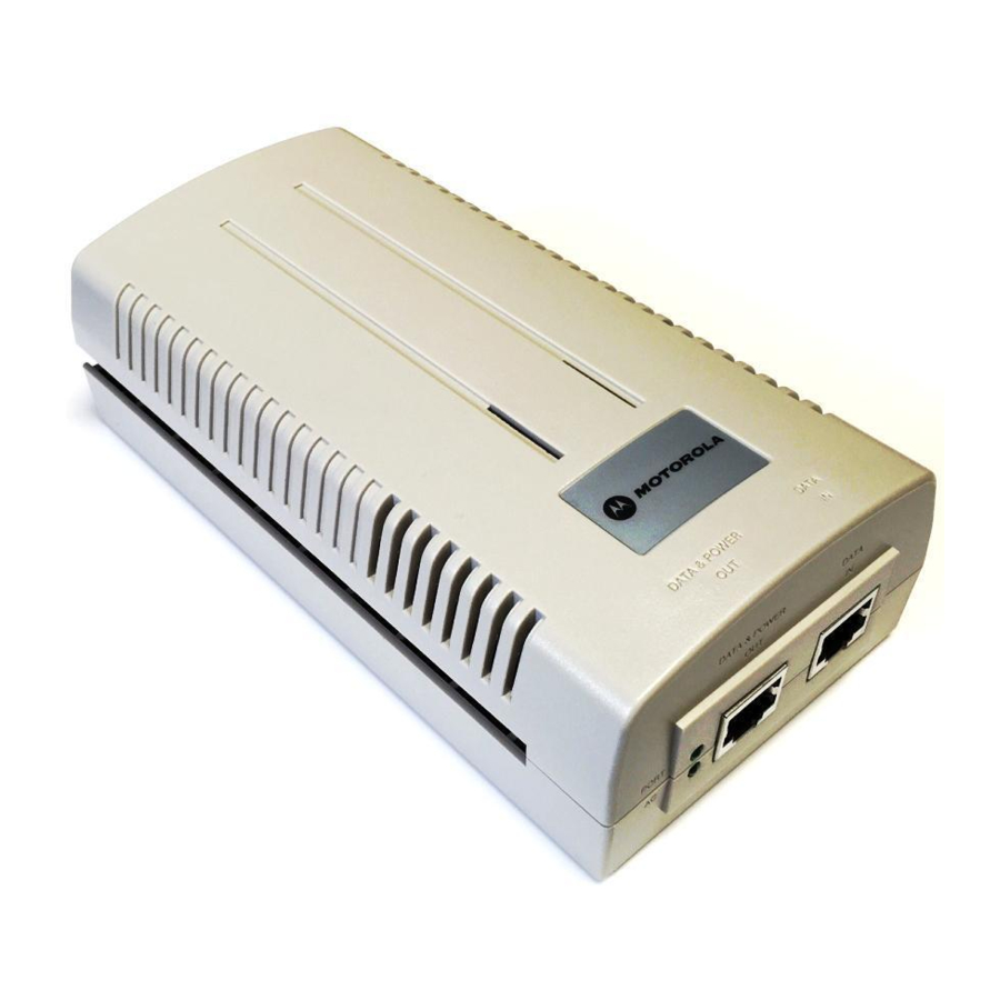
Product Description
The Motorola Power Injector (pt # AP-PSBIAS-1P2-AFR) is a single-port, 802.3af compliant Power over Ethernet hub combining low-voltage DC with Ethernet data in a single cable connecting to an AP. The Power Injector's single DC and Ethernet data cable creates a modified Ethernet cabling environment eliminating the need for separate Ethernet and power cables.

The Power Injector is a small lightweight unit with a RJ-45 Ethernet cord input connector from the hub on the front right-hand side of the unit and a RJ-45 data and power output connector to the AP on the front left-hand side of the unit. On the back of the unit is a 110-220 VAC power input.
A separate Power Injector is required for each device comprising the network. The Power Injector supports the following devices; AP100, AP200, AP300 and AP-5131.

Using the Power Injector with an unsupported Motorola device could render the device inoperable and void your warranty.
The Power Injector has the following features:
- Independent power controller (SPEAR™), CPU controller and input (Data) and output (Data + Power) shielded RJ-45 connectors
- Supports standard 10/100BaseT Ethernet networks over a standard TIA/EIA-568 Category 5 (or higher) cabling
- Meets the IEEE 802.3af standard
- Universal AC Input: 110/220 V, 60/50 Hz.
- Minimum port output continuous allowable power of 15.4W at 48V (minimum 12.95W at the PDTE)
- Underload, overload, short-circuit & under/over voltage port protection.
- Port Status and Main power LED indicators
- Standalone or wall mount installation support
- Interconnection option with other Power Injector units.
Technical Specifications
Physical Specifications
| Width | 58.5mm |
| Height | 31mm |
| Depth | 145mm |
| Weight | 450gr |
Environmental Specifications
| Operating Temperature | 0°C to 40°C (32°F to 104°F) |
| Storage Temperature | -20°C to 70°C (-4°F to 158°F) |
| Operating Humidity | 10% to 93% Non-condensing |
| Storage Humidity | 10% to 93% Non-condensing |
Electrical Specifications
| Input Voltage | 90VAC to 264VAC (47Hz - 63Hz) |
| Maximum Output Power | .15.4 W |
| Nominal Output Voltage | 48VDC |
Ethernet Interface
| Input (Data In) | Ethernet 10/100Base-T (RJ-45 female socket) |
| Output (Data & Power Out) | Ethernet 10/100Base-T, plus 48VDC RJ-45 female socket, with DC voltage on pairs 7-8 and 4-5 |
Installation
Preparing for Site Installation
The Power Injector can be installed free standing, on an even horizontal surface or wall mounted using the power injector's wall mounting key holes.
The following guidelines should be adhered to before cabling the Power Injector to the Ethernet source and Motorola device:
- Verify the device receiving converged power and Ethernet from the Power Injector is a product approved by Motorola (AP100, AP200, AP300 and AP-5131).
- Do not block or cover airflow to the Power Injector.
- Keep the Power Injector away from excessive heat, humidity, vibration and dust.
- The Power Injector is not a repeater, and does not amplify the Ethernet data signal. For optimal performance, ensure the Power Injector is placed as close as possible to the network data port. Do not configure the cable length between the Ethernet network source, the Power Injector and the Motorola AP beyond 100 meters (333ft).
Cabling the Power Injection
To install the Power Injector to an Ethernet data source and Motorola device:
Ensure AC power is supplied to the Power Injector using an AC cable with an appropriate ground connection approved for the country of operation.
- Connect the Power Injector to an AC outlet (110VAC to 220VAC).
- Connect RJ-45 Ethernet cable between the network data supply (host) and the Power Injector Data In connector.
- Connect a RJ-45 Ethernet cable between the Power Injector Data & Power Out connector and the Motorola device receiving converged power and Ethernet.
Ensure the cable length from the Ethernet source (host) to the Power Injector and Motorola device receiving converged power and Ethernet does not exceed 100 meters (333 ft).

The Power Injector has no On/Off power switch. The Power Injector receives power and is ready for Motorola device connection and operation as soon as AC power is applied.
Multiple Power Injection Installations
Each Power Injector has a coupling rail designed to connect Power Injectors together to support multiple device installations. Align the power injectors and slide the units together using the coupling rail to connect the units. Cable each device as described in the Cabling the Power Injector section of this document. Only one Motorola device (AP 100, AP 200, AP 300 or AP-5131) can be powered from a single Power Injector.
Power Injection LED Indicators
The Power Injector demonstrates the following LED behavior under normal and/or problematic operating conditions:

| LED | AC (Main) | Port |
| Green (Steady) | Power Injector is receiving power from AC outlet | Indicates a device is connected to the Power Injector's outgoing Data & Power cable |
| Green (Blinking) | Output voltage source is out of range | The Power Injector is overloaded or has a short circuit |
Troubleshooting
The following potential Power Injector problem scenarios should be addressed as follows:
Power Injection does not power up properly
- Verify the power cord power cord is operational for the intended country of operation
- Verify the voltage at the power inlet is between 100 and 240 VAC.
- Remove and reapply power to the Power Injector and verify the LED behavior during the powering sequence.
A Power Injector port indicator is not illuminated and the Motorola AP does not operate
- The Power Injector did not detect the AP and thus the port is not enabled.
- Ensure you are using a standard 5/5e/6, straight-wired cable with four pairs.
- Verify the input Ethernet cable is connected to the Power Injector Data In port.
- Verify the Motorola AP is connected to the Power Injector Data & Power port.
- Reconnect the Motorola AP to a different Power Injector. If the AP receives power, there is probably a faulty port or RJ-45 connection on the Power Injector.
- Verify there is not a short over any of the twisted pair cables or over the RJ-45 connectors.
Access Point receives power but no Internet
- Verify the Ethernet cable is connected to an active hub or switch port on the network.
- Verify the port indicator on the front panel is continuously illuminated.
- Verify you are using a standard UTP/FTP Category 5 straight (non-crossover) cabling with all four pairs.
- Ensure the Ethernet cable length is less than 100 meters from the Ethernet data source to the Power Injector.
- Reconnect the Motorola AP to a different Power Injector. If the AP receives power, there is probably a faulty port or RJ-45 connection on the Power Injector.
Customer Support
Motorola provides its customers with prompt and accurate customer support. Use Support
Central as the primary contact for any technical problem, question or support issue involving Motorola products. If the Support Central specialists cannot solve a problem, access to all technical disciplines within Motorola becomes available for further assistance and support. Motorola Support Central responds to calls by email, telephone or fax within the time limits set forth in individual contractual agreements. When contacting Support Central, please provide the following information:
- Serial number of unit
- Model number or product name
- Software type and version number

Documents / ResourcesDownload manual
Here you can download full pdf version of manual, it may contain additional safety instructions, warranty information, FCC rules, etc.
Download Motorola AP-PSBIAS-1P2-AFR - Power Injector Installation Guide
Advertisement


Need help?
Do you have a question about the AP-PSBIAS-1P2-AFR and is the answer not in the manual?
Questions and answers