Table of Contents
Advertisement
Quick Links
Advertisement
Table of Contents

Related Manuals for Technische Alternative C.M.I.


Summary of Contents for Technische Alternative C.M.I.
- Page 1 C.M.I. Control and Monitoring Interface Version 1.28 User manual...
-
Page 2: Hardware / General
Hardware / General... - Page 3 Function The control and monitoring interface ("C.M.I." for short) is a web server that creates a connection between a LAN network and the CAN bus components. This device makes it possible to load function data into CAN bus devices, update and remote control them, illustrate online diagrams and log data. Access can be local directly from the PC/network, via Internet and the C.M.I.
-
Page 5: Power Supply
Power supply Operation of the C.M.I. requires 12V supply from CAN bus or a 12V-power pack. Power is not supplied via DL bus. Power consumption: typically 1.5 W If there is only one controller (UVR1611, UVR16x2, RSM610) in the network, it is essential to use a 12 V power supply unit to ensure power to other CAN bus subscribers that do not have their own supply. - Page 6 CAN bus Next to data transfer, the CAN bus offers also the possibility to directly access the devices in the CAN network from the PC via browser. Termination Correct termination of the buses is important for use of the CAN bus to connect several devices. The network must have terminations at the ends of the lines.
- Page 7 Recording of network variables is therefore not possible, if two controllers are connected with the C.M.I. (this note applies only to data recording via DL bus). logging“ of the The scope for data recording of this 2nd virtual UVR1611 in the menu “Settings/Data C.M.I.s must be set like this:...
- Page 8 Commissioning UVR1611 compatibility information In order to be able to access the full range of functions, the controller must have at least operating system version A3.25.
-
Page 9: Delivery Scope
Delivery scope The delivery scope of the device includes the following parts: 1 pc. Control and Monitoring Interface C.M.I. 1 pc. SD card 1 pc. 4-pole plug for the CAN bus 1 pc. 3-pole plug for the DL bus 1 pc. Brief guide 1 pc. -
Page 10: Mounting And Connection
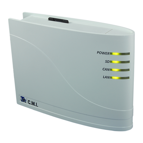
Mounting and connection The C.M.I. can be assembled either with 2 screws on an even surface or with the enclosed rapid mounting to a TS35 DIN rail according to the EN 50022 Standard. Dimensions: Connections Connections are labelled and must not be confused. The following Figure also shows termination on the left (CAN bus). - Page 11 The POWER LED now has to be green permanently.
-
Page 12: Fixed Ip Address
IP-Address Access requires an IP address. Network with DHCP server (standard) The network settings are determined automatically. Network without DHCP server Direct C.M.I. connection– Windows PC DHCP must be activated on the PC.PC and C.M.I. automatically gets an IP address this way. This process can take more than 1 minute. -
Page 13: Access Via Browser
Access via browser... - Page 14 Access via LAN or port forwarding 1. Browser start 2. Entry in the address field of the browser: cmi (factory setting, only under Windows) or IP address Entry „cmi“ Entry IP address (example) The language in this window depends on the language setting in the PC operating system. 3.
- Page 15 Further operation is described in chapter "C.M.I. menu".
- Page 16 IIf you want access via Internet, then the C.M.I can be connected via “„C.M.I. web portal“. The C.M.I. web portal is a server that was set up by Technische Alternative. 1. Select the address https://cmi.ta.co.at, „Log in“ and click "Registration".
- Page 17 Caution: All warranty and guarantee claims become void if the rating plate or key label is removed! The "Designation“ helps with the selection of several individual C.M.I.s and is visible in the list of individual C.M.I.s. If service by the super user (e.g. Technische Alternative) is to be allowed at all times, the...
- Page 18 After clicking on “Add“, a message about successful addition is displayed. After updating the page, the C.M.I. appears in the list “My C.M.I.s“. 8. After updating the page, the C.M.I. appears in the list “My C.M.I.s“. Clicking on the serial number takes you to the C.M.I. menu.
-
Page 19: Resetting And Loading Of Factory Settings
Resetting and loading of factory settings Briefly pressing the reset key on the rear of the C.M.I. restarts the C.M.I. (reset). If the reset button is pressed and released while the red LEDs are still illuminated, resets the C.M.I. to factory settings. - Page 20 Web portal cmi.ta.co.at...
- Page 21 Menu Account management Contact information and password can be changed in this menu. The current password must be entered to finalise every change. It is also possible to delete the user. During the log, it can be specified that the user always stays logged in when selecting the web portal: All saved user settings can be deleted in the account management menu.
- Page 22 Menu C.M.I.s Example of a user who already has registered an individual C.M.I. (CMI003780) and to whom another user (stefan) has granted access to his/her C.M.I. (CMI000533):...
- Page 23 1. Add C.M.I. This application is described in the chapter “Access via C.M.I. web portal https://cmi.ta.co.at “.
- Page 24 2. My C.M.I.s All C.M.I.s of the logged in user are listed here with a shortcut. Clicking on the serial number takes you to the C.M.I. menu (see chapter “C.M.I. menu“).
- Page 25 3. Management a) Clicking on the next to the serial number deletes this C.M.I. and it can no longer be selected. b) The summary and the description of the C.M.I. can be changed here. c) Click on “Save“ to finalise changes. d) In the submenu “Manage”, remote maintenance can be authorised directly for another user whose login name is known.
- Page 26 The released C.M.I. for which remote maintenance as expert was granted is now shown to user “rim“ in the menu “C.M.I.s” under “Other C.M.I.s“.
- Page 27 • CAN-EZ2 • CAN-MTx2 Settings can only be made by the owner of the C.M.I. (displayed under "My C.M.I.s") or by an expert for whom the C.M.I. has been enabled (displayed under "Other C.M.I.s"). Owners can: - Alter logging values...
- Page 28 - Alter logging values - Create display profiles - Add their own display profiles for the owner - See and edit the owner display profiles if these are enabled by the owner - Create diagrams Users/guests can: - See display profiles enabled by the owner - Create diagrams...
- Page 29 Managing logging values Before profiles can be defined and diagrams can be loaded, the logging values must be set. This menu is used to determine which values should be logged. Up to 40 values (analogue or digital) can be selected. Inserting It is possible to log values for the 4 available devices in this system.
- Page 30 It is also possible to select several values and drag them into the right-hand field at the same time by clicking them whilst holding down the Shift or Ctrl key. Additional values must be dragged into the area for the logging values which have already been created.
-
Page 31: Logging Interval
In this example, 13 out of 40 possible logging values have been inserted. Special cases for outputs: Mixer outputs could not be logged. Both a digital value (ON/OFF) and an analogue value (speed stage) can be selected for variable speed triac outputs (wave packet control). - Page 32 Updating In the case of a CAN node failure (logging values for this node are displayed as 0 in the diagram), "Update" checks whether all values to be logged are able to be called up. Example: The node for the first three values, which are shown with a red dot, has failed. The node for the fourth value is active.
-
Page 33: Adding A Profile
If the profile is created as an expert for whom the C.M.I. has been enabled (displayed under "Other C.M.I.s"), then the user can determine whether a new profile should be inserted for the owner or whether it should be visible only to the user. - Page 34 Managing display profiles After selecting the required profile, click the "Manage display profiles" icon. Enabling The owner can enable the profile for experts, users or guests (who have permission to access the C.M.I.) or for nobody. Chapter "Visualisation" describes which actions the respective user is permitted to carry out.
- Page 35 Clicking the colour opens up a selection window where a different colour for the graphs can be chosen.The language in this window depends on the language setting in the PC operating system. Once all values for the diagram have been defined, click "Save" at the end of the list. If saving is successful, a message appears to this effect.
- Page 36 Loading the diagram After the profile and display period have been selected, click "Load". With a logging interval of 1 minute (setting under "Manage logging values"), after a period of 7 days logging values are filtered for the display, in order to prevent the diagram from taking too long to load. This means a maximum of 10080 (= 7 x 24 x 60) logging times are displayed in one diagram.
- Page 37 The scale for the analogue values is set automatically according to the highest displayed value. If the cursor is placed over a value, the relevant value is shown in bold.
- Page 38 Clicking the icon hides the value and the scale is adjusted to the highest displayed value.
- Page 39 Moving the cursor onto the diagram displays a time line with time and date information and the value nearest to the cursor for this time point. It is possible to zoom in on the time axis by dragging one of the dots shown by the red arrow.
- Page 40 Dragging the time line in the diagram whilst holding down the left mouse button allows you to zoom in on the selected time period.
- Page 41 Digital values The ON/OFF status of the digital values is displayed above the analogue values. Zooming in on the time axis always applies to both digital and analogue values.
- Page 43 The queried user will immediately get a mail with a link to click. If a request for remote maintenance was made, the following can be seen in the "Remote maintenance" area under "My C.M.I.s", after you click on management: The user “rim“ (=login name) has submitted a remote maintenance request.
- Page 45 6. Other C.M.I.s Here the C.M.I.s of other users are displayed for which the logged in user has been given permission for remote maintenance. Example: Clicking on the serial number takes you to the C.M.I. menu (see chapter “C.M.I. menu“).
- Page 46 Operation via web portal (Internet): Entry of the C.M.I. web portal name (https://cmi.ta.co.at) and log in. Selection of the tab "C.M.I.s“ and clicking on the serial number of the desired C.M.I.. A new tab with the designation of the device opens.
- Page 47 Menu Home The 1st page (Home) shows the operating status of the C.M.I. with the LEDs. The actual status of the LEDs is shown. The current LED status is explained on the side. Six different states are possible: green, orange, red, permanently lit or flashing. Example: Failure of a CAN network node.
- Page 48 no SD card inserted green everything ok (at least one additional CAN node found) orange not all essential nodes for logging available one node has failed no CAN network available green everything ok green no reverse connection to the web portal (if selected in the flashing Ethernet menu) error...
- Page 49 Menu CAN-Bus This menu shows the devices in the CAN bus network with their designation and node number displayed. The C.M.I. has node number 56 with factory settings. Example of a CAN network with one controller UVR16x2, one controller UVR1611, one CAN I/O 45 module and one RSM610 module: Clicking on one of the devices takes you to the device menu.
- Page 50 The view is comparable to the view on the controller display. Selecting a menu item takes you to the selected submenu. Example: Programming the parameters for Input 1 When the "Inputs" menu item is selected, a page appears that has the same layout as the controller. Selecting the required input takes you to the following display:...
- Page 51 When you select the parameter you want to modify, a dropdown list appears: Select the required parameter and complete the modification procedure with "OK". Example: UVR1611 The top row displays, as familiar from the controller, the status of the outputs: Highlighted in black: Output ON The hand symbol means manual mode.
- Page 52 Clicking on an arrow takes you to the selected sub-menu. This enables direct selection of the most important submenus (exception: “User” menu). Using the back function displays the page shown last. This may no longer show back current values. This button reloads the displayed page with current values. reload “Main menu“...
- Page 53 Clicking the arrow symbol of the corresponding parameter to be changed displays a selection list with possible adjustment parameters. After making a selection by mouse clicking, the new controller parameter is immediately transferred via the CAN-bus. The controller saves the parameters and returns the corrected menu page which is reloaded by the browser.
- Page 54 The change is displayed after the node number has been modified.
-
Page 55: Menu Diagram
Menu Diagram Selecting this menu item displays the online diagram (if programmed). Programming of the online diagram with “TA-Designer” is described in the program's online tutorial. local Direct access to the online diagram without login can be done by entering the following URL: http://user:password@cmi/schema.html#1 User: user name for expert, user or guest Password: password defined for the respective user... - Page 56 Menu Data administration In the left part of the window, the active (connected) CAN bus devices are displayed, and in the right part the SD card with the function data and firmware files saved to the SD card. Updating the C.M.I. If the button "Update C.M.I."...
- Page 57 The network node is dragged to the SD card symbol with drag & drop. The function data are copied to the SD card. This is followed by a display indicating successful or unsuccessful download: Function data of Bootloader BL-NET cannot be copied to the SD card this way. 2.
- Page 58 The upload is started with drag & drop from the list of function data or firmware to the device symbol. This allows devices on the CAN bus – including the C.M.I. – to be updated. A UVR16x2 controller update (= firmware upload) is only possible from controller version 1.20. It is not possible to update a BL-NET bootloader If a file was dragged to an incorrect device that is not compatible with this file, there will be an ERROR message.
- Page 59 If the CAN connection is interrupted during the firmware update of a UVR1611, then the controller in node 63 is without operation system. For a new start of the firmware update again, drag the controller firmware to the C.M.I. icon as an exception. 4.
- Page 60 Highlight the desired file and click on “Rename“. In the subsequently displays window, enter the new file name and confirm with Ok.
-
Page 61: Menu Settings
Menu Settings... -
Page 62: Ethernet (Lan Settings)
Ethernet (LAN settings) If more than one C.M.I. is used in the same LAN network, then these C.M.I.s must have different host names. In this example, the host name was changed to "CMI1". The host name can be freely selected and does not require a reference to the word “CMI“. - Page 63 In order to enable the "Update C.M.I" button to be displayed, outgoing port 80 must not be blocked by any existing firewall. Direct connection C.M.I. - PC DHCP is activated in the factory setting. The C.M.I. tries to obtain a valid IP address from the network on its own.
-
Page 64: Can Settings
CAN settings The CAN node number and the bus rate of the C.M.I. can be changed in this submenu. Every CAN bus participant must have an individual node number in the CAN network. The C.M.I. has node number 56 with factory settings. The C.M.I. - Page 65 Messages The values and conditions for mail and SMS dispatch can be determined in the menu “Messages”. It is only possible to send text messages with the built-in GSM module. The values are adopted from the C.M.I. inputs. Up to 32 messages are available. Example for a message in case of excess collector temperature: Message designation Select the input type (CAN bus, Modbus or data link)
-
Page 66: Automatic Messages
SMS dispatch and SMS query are described in the manual for the GSM module. Automatic messages Electricity failure In case of electricity failure, an SMS can be sent only via the GSM module (description in the GSM module manual). Node failure In the event of a CAN node failure, an email message can be sent, and with an installed GSM module an SMS message can be sent. - Page 67 Contacts E-mail addresses and phone numbers for text messaging are entered in this menu. It is only possible to send text messages with the built-in GSM module. Up to 8 contacts can be listed and tested. The phone numbers must begin with the international area code (e.g. +44 ...or 0044...). The language setting relates to the correct format for controller values and units which can be sent in a message.
- Page 68 Passwords User names and passwords for different user levels are defined here. Only the user name and the password for the expert (admin/admin) are pre-set in the factory settings. Password settings can be changed by registered experts only. Passwords may not include special characters or umlauts ("ä, ü, ö"). Password entry must be repeated as a precaution.
- Page 69 cmi: host name or IP address of the C.M.I. xxxxxx: entry of the required URL...
-
Page 70: Data Logging
Data logging The datalogging settings for readout with Winsol are found in this menu. You can log either from the DL bus (max. 2 data lines) or from the CAN bus (max. 8 data records). The data is saved to the SD card. Example: CAN data logging of data records of node 1 (e.g. - Page 71 Only 1 data record or 2 data records will be logged, depending on the settings in the controller's menu under Settings / Datalogging. The number of data records depends on the following rule: If at least a higher or equal analogue value is assigned to the number 17, then a 2nd data record is automatically created for this controller.
-
Page 72: Time Settings
Time settings Source of supply: The C.M.I. accepts the time-stamp either from an adjustable NTP server (default setting: 3.at.pool.ntp.org) or from the CAN network (UVR1611 with node number 1) or via one of the two data lines (DL bus) of the respective connected controllers. Automatic switch to summer time takes place according to the specifications of the European Union. - Page 73 Inputs All settings for values which can be adopted by the C.M.I. via CAN bus, Modbus/TCP, DL bus or SMS can be found in this menu. These values can then be transferred to C.M.I. outputs or used for messages.
- Page 74 CAN bus Setting the values which are adopted from the CAN bus. Up to 64 analogue and 64 digital values can be defined. Example: adoption of the analogue CAN network output 1 of the CAN node 1 in the analogue CAN bus input 1 of the C.M.I.
- Page 75 Because no new value was issued within 5 minutes, the output value of 100 °C is adopted and timeout is displayed.
- Page 76 Modbus Setting the values which are read out from the Modbus device. Up to 64 analogue and 64 digital values can be defined. In this case, the C.M.I. is the master and the requested value comes from the slave. Example: analogue temperature value Input designation Enter the IP address and the manufacturer-specific data for the Modbus value which is being read out.
- Page 77 User defined output value for timeout. Depending on the unit, this value is issued with the appropriate number of decimal places (example: "50" is issued if the temperature is "50.0 °C"). Actual value: this value is currently adopted by the C.M.I., subject to the factor, the unit and the timeout settings.
- Page 78 Data link Setting the values which are adopted from the DL bus. Only values from the DL data frames of the devices, which are also used for DL datalogging, can be adopted. Values from DL sensors cannot be read. Up to 32 analogue and 32 digital values can be defined. Example: analogue value 1 from DL1 Input designation Bus: enter the data link connection on the C.M.I., via which the value should be read.
- Page 79 Input 9 Sensor value 9 Ext. value 6 Ext. value 3 Input 10 Sensor value 10 Ext. value 4 Input 11 Sensor value 11 Ext. value 5 Input 12 Sensor value 12 Ext. value 6 Input 13 Sensor value 13 Ext.
- Page 80 This function is only possible if a GSM module is fitted. This menu is used for entering the designations and settings for SMS commands. Up to 16 SMS commands for analogue values and 16 for digital values can be defined. If an SMS message is transmitted to the GSM module with the designation (along with value and call sign), an SMS input is generated which can then act as the source for a CAN output, for example.
- Page 81 Example: SMS with the designation "heating" for operating mode changeover of a heating circuit With the additional texts standby, time, normal, lowered and internal, the operating mode of a heating circuit can be changed via SMS. These commands are adopted by the C.M.I. as analogue numbers and can be passed on to the CAN network (CAN output of the C.M.I.).
-
Page 82: Digital Commands
normal Alternative value lowered Alternative value internal Alternative value Note: Settings time > 0 and alternative value 0: at the end of the time, after the value 64-67 or 127 has been transferred, the C.M.I. issues the alternative value 0. The alternative value 0 does not result in any further changes in the heating circuit controller. - Page 83 Outputs In this menu, values from C.M.I. inputs can be linked with CAN bus or Modbus outputs of the C.M.I. or transmitted to other C.M.I.s via LAN using "CoE".
- Page 84 CAN bus Setting the values which are transferred to the CAN bus for use in other CAN bus devices. Up to 32 analogue and 32 digital values can be defined. Example: adoption of the analogue DL input 1 Output designation Select the input type: Modbus, Data link or SMS.
- Page 85 Interval time 5 The value is transmitted every 5 minutes even if it has not changed since the last transmission (minimum value: 1 minute). Actual value: this value is currently being issued by the C.M.I. After completing the entry: Save...
- Page 86 Modbus Setting the values which are transferred to the Modbus for use in Modbus devices. In this case, the C.M.I. is the master and the value is transmitted to the slave. Up to 32 analogue and 32 digital values can be defined. Example : a CAN input value is transferred to a Modbus device Output designation...
- Page 87 Transmission conditions for analogue Modbus outputs: If change > 3 If the current value has changed by more than 3 compared to the last transmitted value, a new transmission is made. Blocking time 10 If the value changes by more than 1 within 10 seconds of the last transmission, the value is still only retransmitted after 10 seconds (minimum value: 1 second).
- Page 88 CoE (= CAN over Ethernet) Description of the data transfer method Using this method, it is possible to transfer the values of analogue and digital C.M.I. inputs to other C.M.I.s via Ethernet (LAN). This means data can be exchanged between separate CAN networks.
- Page 89 Output designation Select the input type: CAN bus, Modbus, Data link or SMS. Select the required input Transfer the measured value (currently no other entry possible) Enter the IP address of the receiving C.M.I. to which the value is transmitted Enter the CAN node number: the receiving C.M.I.
- Page 90 Interval time 5 The value is transmitted every 5 minutes even if it has not changed by more than 3 since the last transmission (minimum value: 1 minute). Transmission conditions for digital CoE outputs: If change yes/no Transmission of the value if a status change occurs Blocking time 10 If the value changes within 10 seconds of the last transmission, the value is still only retransmitted after 10 seconds (minimum value:...
-
Page 91: Menu Status
Menu Status This menu provides information above files saved to the SD card and other states of the C.M.I.. - Page 92 SD card If an SD card other than the supplied one is used, then the following must be observed: The SD card must be formatted with the FAT16 or FAT 32 file format. SD cards with a memory of up to 4 GB can be used without problems. SD cards with a memory of up to 32 GB can be used but the display of available memory may be incorrect.
- Page 93 Clicking on this button deletes the txt file in the folder event_log (event and error memory). Copy the SD card's files to the computer Click on the file in question with the right mouse button and select the target on the computer.
- Page 94 TCP sockets This page provides an overview of possible network connections and is especially helpful for experts during the error analysis of network problems.
- Page 95 CAN-Bus In this submenu, the CAN bus status can be checked. Every CAN bus device sends a Heartbeat to the C.M.I. every 10 seconds. If there is no signal after 15 seconds, “Timeout“ is displayed for the node. Example: Timeout of node 32 Clicking on the node number in this submenu takes you directly to the menu of the respective device.
- Page 96 DL-Bus In this submenu, the DL bus status can be checked. If there is no signal after 15 seconds, “Timeout“ is displayed for the data line. In the above example, only one data line is connected so a timeout is visible only with DL2.
- Page 97 Logging In this status menu, it can be checked whether the set logging method works. In addition, it can be checked whether the system time is valid. There will be no logging without a valid system time. Brief lapses of the green “POWER“ LED at regular intervals indicates active data logging...
- Page 98 This page shows the current "CAN over Ethernet" (CoE) data transfer. For more detailed information about "Outputs/CoE (= CAN over Ethernet)". CoE, see chapter...
-
Page 99: Ec Declaration Of Conformity
EC-DECLARATION OF CONFORMITY... -
Page 100: Guarantee Conditions
Legal notice These assembly and operating instructions are protected by copyright. Use outside the copyright requires the consent of the company Technische Alternative RT GmbH. This applies in particular to reproductions, translations and electronic media. Subject to technical modifications ©... - Page 101 By using this website, you consent to the processing of data about you by Google in the manner and for the purposes set out above. Technische Alternative RT GmbH A-3872 Amaliendorf, Langestr. 124...
Need help?
Do you have a question about the C.M.I. and is the answer not in the manual?
Questions and answers