
Related Manuals for Technische Alternative C.M.I.


Summary of Contents for Technische Alternative C.M.I.
- Page 1 C.M.I. Version 1.04 Manual version 1 Control and monitoring Interface Operation Winsol 2.01 TA-Designer 1.08...
-
Page 2: Table Of Contents
Access via C.M.I. web portal https://cmi.ta.co.at ................. 8 Resetting and loading of factory settings .................. 11 Web portal cmi.ta.co.at ......................11 Menu Account management ...................... 11 Menu C.M.I.s ..........................11 Add C.M.I........................11 My C.M.I.s ........................12 Manage ........................12 Request remote maintenance .................. - Page 3 General toolbar ..........................35 Language ............................. 35 Basic settings ..........................35 Setup dialogue..........................36 1. Window: Data logger/connection ................... 36 2. Window: Data recording ......................37 3. Window: Measured value descriptions .................. 38 Customer mode ........................... 38 Add new customer ........................38 Open customer .........................
-
Page 4: Hardware/General
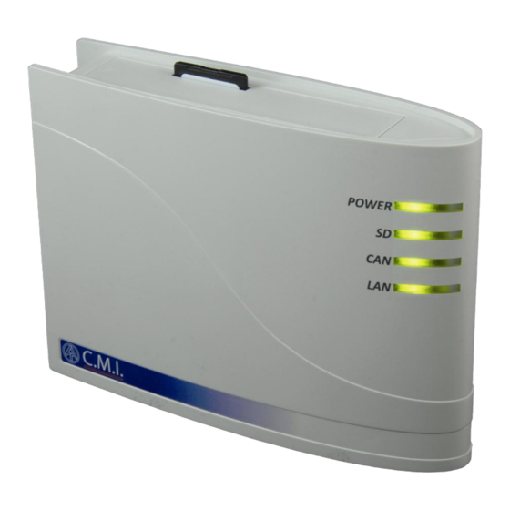
Hardware/General Hardware/General Function The control and monitoring interface (abbreviation: C.M.I.) is a web server that can create the connection between a LAN network and the controller UVR1611 with its CAN bus compo- nents. This device makes it possible to load function data into CAN bus devices, update and remote control them, illustrate online diagrams and log data. -
Page 5: Dl Bus
Recording of network variables is therefore not possible, if two controllers are connected with the C.M.I. (this note applies only to data recording via DL bus). The scope for data recording of this 2nd virtual UVR1611 in the menu “Settings/Data logging“ of the C.M.I.s must be set like this:... -
Page 6: Commissioning
Commissioning Commissioning Delivery scope The delivery scope of the device includes the following parts: 1 pc. Control and Monitoring Interface C.M.I. 1 pc. SD card 2 GB 1 pc. 4-pole plug for the CAN bus 1 pc. 3-pole plug for the DL bus 1 pc. -
Page 7: Making The Connections
Commissioning Making the connections Connections must be made in the following sequence 1. Connection LAN cable 2. Connection CAN bus or DL bus cable 3. Optional: power supply with power unit The POWER LED now has to be green permanently. IP-Address Access requires an IP address. -
Page 8: Access Via C.m.i. Web Portal Https://Cmi.ta.co.at
Access via C.M.I. web portal https://cmi.ta.co.at If you want access via Internet, then the C.M.I can be connected via “„C.M.I. web portal“. The C.M.I. web portal is a server that was set up by Technische Alternative. and click “Registration“. 1. Select the address... - Page 9 This process can take up to 30 minutes. 4. After clicking the link, the start page of the web portal is displayed already. 5. Adding the C.M.I. in the Web portal Selection of the tab “C.M.I.s“ 6. Selection “Add C.M.I.“...
- Page 10 On the rear of the device is the serial number on the rating plate and the key on the key label. The key must be entered without spaces. 8. After updating the page, the C.M.I. appears in the list “My C.M.I.s“. Clicking on the serial number takes you to the C.M.I. menu.
-
Page 11: Resetting And Loading Of Factory Settings
The current password must be entered to finalise every change. It is also possible to delete the user. Menu C.M.I.s Example of a user who already has registered an individual C.M.I. (CMI000501) and to whom another user (stefan) has granted access to his/her C.M.I. (CMI001015): 1. -
Page 12: My C.m.i.s
Web portal C.M.I.s All C.M.I.s of the logged in user are listed here with a shortcut. Clicking on the serial number takes you to the C.M.I. menu (see chapter “C.M.I. menu“). 3. Manage a) Clicking on the next to the serial number deletes this C.M.I. and it can no longer be selected. - Page 13 The released C.M.I. for which remote maintenance as expert was granted is now shown to user “rim“ in the menu “C.M.I.s” under “Other C.M.I.s“. This shows under “My C.M.I.s” that one request for remote maintenance was made: After clicking on Administration, you can see in the area " Remote maintenance “:...
-
Page 14: Request Remote Maintenance
After clicking on the link, the addition al C.M.I. in the menu “C.M.I.s”. 5. Other C.M.I.s Here the C.M.I.s of other users are displayed for which the logged in user has been giv- en permission for remote maintenance. Example: If “Info“ is clicked, the window “C.M.I. Info“ (see item 3. “Manage“) is displayed. -
Page 15: Menu
(https://cmi.ta.co.at) and log in. Selection of the tab "C.M.I.s“ and clicking on the serial num- ber of the desired C.M.I.. A new tab with the designation of the device opens. There are 6 different submenus that are described in the following:... -
Page 16: Menu Home
CMI menu Home Menu Home The 1st page (Home) shows the operating status of the C.M.I. with the LEDs. The actual status of the LEDs is shown. The current LED status is explained on the side. Six different states are possible: green, orange, red, permanently lit or flashing. Example: Failure of a CAN network node. -
Page 17: Menu Can-Bus
C.M.I. menu CAN bus Menu CAN-Bus This menu shows the devices in the CAN bus network with their designation and node num- ber displayed. The C.M.I. has node number 56 with factory settings. Example of a CAN network with one controller UVR1611, one CAN I/O module and one CAN –... -
Page 18: Remote Maintenance
C.M.I. menu CAN bus Remote maintenance Example: UVR1611 node 1 Only the values current at the time of loading of the page that are displayed. In order to display the actual (latest) values, the page must be refreshed. The top row displays, as familiar from the controller, the status of the outputs: Highlighted in black: Output ON The hand symbol means manual mode. - Page 19 C.M.I. menu CAN bus Example: Parameterisation input 1 After selection of the menu item “Inputs” a page is displayed, which has the same layout as in the controller. By clicking the arrow next to the desired input, the following display is brought up: Clicking the arrow symbol of the corre- sponding parameter to be changed dis- plays a selection list with possible adjust-...
- Page 20 C.M.I. menu CAN bus Example: Changing the mode number of the CAN I/O module from 32 to 31 “Network“ menu of the CAN I/O module Select the new node number and confirm with “REALLY CHANGE?“ with “yes”. The change is displayed after the node number has been modified.
-
Page 21: Menu Schematic
CMI menu Data administration A missing CAN node is indicated by the red LED for the CAN bus on the C.M.I.. This display is also visible in the browser in the menu “Home“. “CAN reload“ reloads the network nodes and all non-existing nodes are no longer displayed with timeout. -
Page 22: Download Of Function Data From Devices To Sd Card
C.M.I. menu Data administration 1. Download of function data from devices to SD card The network node is dragged to the SD card symbol with drag & drop. The function data are copied to the SD card. This is followed by a display indicating successful or unsuccessful download: Function data of Bootloader BL-NET cannot be copied to the SD card this way. -
Page 23: Upload Of Function Data And Firmware From Sd Card To Devices
C.M.I. menu Data administration 3. Upload of function data and firmware from SD card to devices The upload is started with drag & drop from the list of function data or firmware to the device symbol. All devices in the CAN bus, including the C.M.I., can thus be updated. Update of boot loader BL-NET is not possible. -
Page 24: Download Of Function Data Or Firmware From Sd Card To Pc
C.M.I. menu Data administration 4. Download of function data or firmware from SD card to PC Highlight the desired file and click on “Download“. “Save file“ copies the file to the download folder of the browser where it can be moved to anoth- er folder. -
Page 25: Menu Settings
Menu Settings Ethernet (LAN settings) If more than one C.M.I. is used in the same LAN network, then these C.M.I.s must have different host names and MAC addresses. In this example, the host name was changed to “CMI1“ and the MAC address (the last two digits) modified. -
Page 26: Connection Without Dhcp
C.M.I. menu settings Connection without DHCP The user can specify the parameters (IP address etc.) manually. This can be done in the web interface. If access via the web interface is impossible, there is the possibility to define a fixed IP address with a file: A text file with the name fix_ip.txt with the desired IP address is created in the root directory of the SD card. -
Page 27: Messages
C.M.I. menu Settings Messages The conditions for mails to be sent with the occurrence of specific events can be defined in the menu “Messages. The values to be monitored are accepted either by CAN or DL bus. Up to 32 messages are available. Example for a message in case of excess boiler temperature: Message designation Selection of the bus: CAN bus or DL bus DL1 or DL2... -
Page 28: Mail Settings
C.M.I. menu settings Mail settings The mail settings of the user and sender and recipient addresses are defined in this menu. Information about SMTP access data is available in the settings of the mail program. The sender address is the address that appears as “Sender“ in the mail to the recipient. Up to 8 recipient addresses can be listed and tested. -
Page 29: Passwords
C.M.I. menu Settings Passwords User names and passwords for different user levels are defined here. Only the user name and the password for the expert (admin/admin) are pre-set in the factory settings. Password settings can be changed by registered experts only. Password entry must be repeated as a precaution. -
Page 30: Data Logging
C.M.I. menu settings Data logging The settings for data logging are made in this menu. Man can log either from the DL bus (max. 2 data lines) or from the CAN bus (max. 8 data records). The data is saved to the SD card. Simultaneous logging from DL and CAN bus is not possible. -
Page 31: Time Settings
C.M.I. menu Settings If the settings for the source and/or the data record of a source are changed, then we rec- ommend restarting the C.M.I. (menu “Ethernet/Restart“) and deleting the memory. After the first logging time, a set-up is carried out in Winsol and completed with “Ok“ so that the C.M.I. -
Page 32: Menu Status
C.M.I. menu status Menu Status This menu provides information above files saved to the SD card and other states of the C.M.I.. SD card If an SD card other than the supplied one is used, then the following must be observed: The SD card must be formatted with the FAT16 or FAT 32 file format. -
Page 33: Tcp Sockets
C.M.I. menu status TCP sockets This page provides an overview of possible network connections and is especially helpful for experts during the error analysis of network problems. CAN-Bus In this submenu, the CAN bus status can be checked. Every CAN bus device sends a Heartbeat to the C.M.I. -
Page 34: Logging
C.M.I. menu status Logging In this status menu, it can be checked whether the set logging method works. In addition, it can be checked whether the system time is valid. There will be no logging without a valid system time. Brief lapses of the green “POWER“... -
Page 35: Winsol (From Version 2.01)
1. Create new data path (e.g. using Windows Explorer). 2. Copy the existing files and folders from the existing data path (e.g. installation path "C:\Programs\Technische Alternative\Winsol\") in to the new path. 3. In the Winsol basic settings, set the new path as a data path. -
Page 36: Setup Dialogue
Winsol Setup dialogue Selection of the data logger, interface, specification of the logger configuration and entry of the device description and the logged values takes place in the menu "File \ Setup". "Next" is used to switch forward to the next setup window, while "Cancel" is used to cancel setup without changing the logger configuration. -
Page 37: Window: Data Recording
Winsol Clearing the data store 3 options are available: automatically After reading out of the memory, it is automatically deleted (recommended). manually After reading out of the memory, a query is displayed asking whether the memory should be deleted. never The memory is not deleted after reading out. -
Page 38: Window: Measured Value Descriptions
Winsol 3. Window: Measured value descriptions A device description and descriptions for the measured values can be specified for all devic- Summary: Selection of the device Device description Description of the analogue and digital values Important: Setup is only completed if the "OK" button has been clicked. -
Page 39: Open Customer
Winsol Open customer An already created customer can be opened in the menu "File \ Open...". Manage customer Customers can be renamed or deleted via the menu "File \ Manage...". Recording of measured values from a customer system There are four options for recording the measured values from a customer system: The C.M.I. -
Page 40: Read Out Logger Data
Winsol Read out logger data Reading out of the logger data is started in the menu "Logger \ Read out data". The data recorded and stored in the CMI are read out and saved as a log file in the Winsol file system on the PC. -
Page 41: Delete Logger Data
Winsol This function is intended for computers that are used solely for data acquisition. In this case, the PC must be automatically booted in a time-dependent manner. For example, this is possible using an external time switch, which supplies the computer with power in a time- dependent manner and if the appropriate BIOS settings have been made (boot up, if supply voltage applied). -
Page 42: Navigation Methods
Winsol Toolbar measured value diagram Standard scaling Y-axis Manage profiles Measured values scaling Auto scaling Y-axis Cursor on/off Grid on/off Zoom out time axis Zoom in time axis Select day (calendar) Next month Previous month Profile display Previous day Next day Navigation methods There are various options and methods, for optimally configuring or changing the graphics display to meet your individual requirements. - Page 43 Winsol Y-axis zooming Navigation Keyboard Mouse Y-axis zooming (+) Scroll "forward" + pressed Ctrl Ctrl key Fixed point is the middle of Fixed point is the position of the diagram the mouse pointer Y-axis zooming (-) Scroll "back" + pressed Ctrl Ctrl Fixed point is the middle of Fixed point is the position of...
- Page 44 Winsol Move cursor in X-axis Navigation Keyboard Mouse Set cursor Double-click with left mouse button (positioning at the closest measuring point) → Measuring point / step for- ward ← Measuring point / step back → min. 1/24 of the display pane Ctrl / step forward ←...
- Page 45 Winsol Highlighting or hiding graphs Clicking a measured value in the right table with the left mouse button causes the value and graph to be especially highlighted. Clicking a measured value in the right table with the right mouse button causes the value and graph to be hidden.
- Page 46 Winsol Measured values scaling This menu option is used for matched scaling of various measured value units. This improves the perceptibility of measured values in the graphic. Grid on/off Makes possible the display and hiding of the grid. Cursor on/off If the cursor is switched off, no measured values are listed on the side and at the top right only the date of the displayed day is henceforth displayed.
-
Page 47: Manage Profiles
Winsol Manage profiles The menu option "Manage profiles" (Manage profiles) is used to select the values to be displayed and the colour of the graph curves. Moreover independent profiles can be created, modified or deleted for various system areas and a separate diagram title specified. Clear the selection of graphs in the profile Delete profile... -
Page 48: Troubleshooting
Winsol Troubleshooting Data transfer from the controller to the data logger is not working. 1. Ensure that the data logger is connected to the controller via the DL-bus or the CAN bus. 2. Check the connections and in particular ensure the polarity is correct. 3. - Page 49 Winsol The log- and csv files are not displayed in the corresponding data path "C:\Programs\..." or the searched for subdirectory itself does not even exist. Under certain circumstances, under Windows 8, Windows 7 and Windows Vista, the files are saved under a user-specific "virtual program path": C:\Users\<USERNAME>\AppData\Local\VirtualStore\Programs\Technische Alterna- tive\Winsol\...
-
Page 50: Online Diagram
Online diagram Online diagram The CMI provides the possibility of an online visualisation in which a graphical image of the current system states is displayed with the web browser via LAN or Internet. The online schematic for the UVR1611 is interactive, i.e. values and setting can also be changed de- pending on programming. -
Page 51: Step-By-Step" Instructions
Online diagram “Step-by-step” instructions Preparation: Create the graphics that are intended for the online schematic (*.gif, *.jpg, *.bmp or *.png format) and provide the function data (*.dat file) for CAN bus devices. Start the program TA-Designer If necessary: Change language and restart program Select the menu "File/New project..."... - Page 52 Online diagram Set up a new page by double clicking on "New page" The following selection window appears: Confirm the "Online schematic BL-net" by pressing "OK" Graphics settings Right-clicking with the mouse on the empty screen symbol of the new page causes a selection field to appear in the bottom bar.
- Page 53 Online diagram Insert the values by drag&drop from the left selection search tree into the page and specify the properties. In the "Elements" area, the following value groups are available: Date and time of the CMI Values of data lines 1 and 2 (Data logging using the DL-bus) Values from UVR1611 function data Values from the function data of a CAN I/O module...
- Page 54 Online diagram CMI data With these data, the time and date can be displayed in the online schematic. Values directly from the function data of a CAN bus device Example: UVR1611 All values specified by the function data of a CAN bus device can be displayed.
- Page 55 Online diagram Object with a frame = selected After the prior positioning of the value, the following display is visible: The frame indicates that the object is selected. Clicking the left mouse key causes a non-selected object to be selected and highlighted with a frame.
- Page 56 Online diagram Properties If a format is assigned to an object, then this format is stored for all subsequent objects of this “group”. Differentiation is made here whether the object is part of the group of changea- ble or non-changeable objects. Double clicking the selected text field "XXX"...
- Page 57 Online diagram Left aligned/right aligned Background colour Changing of the pre-set font and background colours: Default setting: Back- ground transparent. Clicking causes the font or background colour to be displayed in the selection field in which the desired colour can be set. User-defined colours also possible;...
- Page 58 Online diagram Transfer format With ”Transfer format“ you can transfer the format of highlighted text to one or several other text passages: Highlight the text with the required format A single mouse click on the icon in the symbol bar initiates a format transfer to one other text.
- Page 59 Online diagram The positions of all inserted objects are indicated with x/y coordinates. The x-axis is horizontal, the y-axis vertical, the respective zero points are left or top. Specification of the coordinates is based on the alignment of the value (left-aligned, right- aligned or centred).
- Page 60 Online diagram Information about values from the UVR1611 *.dat file For all functions: Enable ... Value If a value is not programmed as "locked" and the source is set to "User", then the function can be switched off or on. Heating circuit: Operating mode Current operating mode (e.g.
- Page 61 The “Link text“ is visible in the online schematic. The text format can also be specified with “Properties”. Example: Link to Technische Alternative Deleting of links The deleting of a link is undertaken by selecting it and then pressing the "Delete" key of the...
- Page 62 Online diagram Insertion of text items The insertion of text items takes place by dragging the "Text" element in the search tree with the mouse button pressed down into the desired position in the graphic ("drag & drop"). Only single-line text is possible. Clicking the left mouse key causes a non-selected object to be selected and highlighted with a frame.
- Page 63 Online diagram Make settings for the online diagram (menu "Edit/Settings...") The settings selected here apply only to the currently displayed page. The following settings can be made in the window: Refresh time: Time interval settings for the updating of the current values (never or adjustable from 30 seconds to 60 minutes).
- Page 64 Online diagram Save the programming under "File/Save project..."; if all values are inserted in the graphic and the properties have been specified. One config.tas and one *.cgi, *.html and graphics file each is created in the folder "CMI“ of the project folder.
-
Page 65: New Page
Online diagram New page The creation of extra pages, which can be selected by links, takes place by double clicking the bottom left "New page" symbol. Selection of the page type " Onlineschema CMI " Right-clicking with the mouse on the empty screen symbol of the new page causes a selection field to appear in the bottom bar. -
Page 66: Saving A Project With Another Name
Online diagram Saving a project with another name An open project can be saved to any folder with a new name with menu item “File / Save project as...”. Switching between projects It is possible to simultaneously load several projects with different names. The project to be displayed and edited is selected via the "Project"... - Page 67 EC- DECLARATION OF CONFORMITY Document- Nr.: / Date TA12027 / 3.10.2013 Company / Manufacturer: Technische Alternative elektronische SteuerungsgerätegesmbH. Address: A- 3872 Amaliendorf, Langestraße 124 Product: The stated above product complies with the following essential requirements: EU requirements: 2006/95/EG Low voltage standard...
- Page 68 Legal notice These assembly and operating instructions are protected by copyright. Use outside the copyright requires the consent of the company Technische Alternative elektronische Steuerungsgerätegesellschaft m. b. H.. This applies in particular to reproductions, translations and electronic media.
Need help?
Do you have a question about the C.M.I. and is the answer not in the manual?
Questions and answers