
Related Manuals for Modern Forms FR-D2102-54U


Summary of Contents for Modern Forms FR-D2102-54U
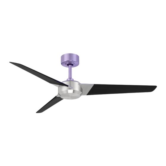
- Page 1 Ultra Germicidal* Smart Fan Installation Instructions works with the Google Assistant *Reduces the SARS COV-2 viruses and other airborne pathogens.
- Page 2 General Inquiries For all questions about your ceiling fan please read all included instructions, installation procedures, troubleshooting guidelines and warranty information before starting installation. Please read and For missing parts or general inquiries call our trained technical staff at: save these instructions 1-866-810-6615 option 0 MON-FRI 8AM-8PM EST before installation...
- Page 3 SUPPORT.” Use only the screws and washers provided with the outlet box. incorporated in the ULTRA in reducing SARS-CoV-2 and other pathogens in the air, Modern Forms makes no claims that its products can cure, treat or prevent any conditions, including COVID-19 or other conditions that may be caused by airborne pathogens.
-
Page 4: Table Of Contents
Get Smart... Contents 1. Mounting Options works with the Integrates Google Assistant 2. Installing the Mounting Bracket seamlessly with: devices you already own 3. Hanging the Fan 3. Hanging the Fan cont. 4. Attaching the Fan Blade 5. Making the Electrical Connections Premium smart Wet Location-listed to the strictest features:... - Page 5 Package Contents Hanging Weight: 20 lbs Blade Set of 3 5. Motor Assembly RPL-F2102-54-BD-** IMPORTANT: Please make note of 6. Aluminum Tray the MAC ID on the receiver and keep it in a safe place. 2. Hanger Assembly - RPL-F-UV7INTRAY-** (UV Module not included) Mounting Bracket Downrod Assembly...
- Page 6 1. Mounting Options CAUTION: To prevent electrical shock, ensure electricity has been turned off at the circuit breaker before beginning. Support Brace If there isn’t an existing UL/cUL listed outlet box, please refer to the 2. Outlet Box following instructions. Secure the outlet box directly to the building 3.
-
Page 7: Installing The Mounting Bracket
2. Installing the Mounting Bracket Remember to disconnect the power at the circuit breaker. To Switch Remove 1 of 2 screws from the bottom of the mounting bracket and save for use in section 11. Loosen the other screw (Fig. 2). 2. -
Page 8: Hanging The Fan Cont
4. Hanging the Fan cont. 5. Align the holes of the downrod and collar and insert the cotter pin and clevis pin. Tighten the two collar screws. (Fig 4B) 6. Slip the coupling cover, canopy screw ring (painted side down), and canopy (opened side up) onto the downrod. -
Page 9: Making The Electrical Connections
5. Making the Electrical Connections WARNING: Installation of this fan requires that a three-conductor cable (including ground wire) which should run between ceiling and wall outlet box. Mounting Bracket WARNING: Check to see that all connections are tight, including 2. Receiver ground, and that no bare wire is visible at the wire nuts, except for the ground wire. -
Page 10: Finishing The Installation
6. Finishing the Installation Secure all wire connections with supplied wire ties to assist in canopy installation. 2. Tuck connections neatly into ceiling outlet box. 3. Slide the canopy up to hanger bracket and place the key hole on the canopy over the screw on the hanger bracket. Turn canopy until it locks in place at the narrow section of the key holes. -
Page 11: Controlling The Fan
NOTE: Only remote controls specifically for the Modern Forms germicidal* UV smart fan can be used with this model (F-RCUV-WT). The remote also cannot be used with other non-UV Modern Forms Fan Your fan was delivered to you with the included control already paired to your fan. -
Page 12: Reset
Scan and follow prompts for instruction In addition to the included remote control, you can control your fan through the Modern Forms app. To use the Modern Forms app, download it for free from the options and Smart Fan FAQs: App Store or Google Play. -
Page 13: Personalize Your Experience
11. Accessories 12. Troubleshooting cont. My Fan is Noisy personalize your experience Bluetooth UV Remote Control Allow for 24-hour break-in period. Most noises associated with a new fan will go away during this time period. ON/OFF 6 fan speeds 2. Check to make sure the screws which attached to the blades (and blade arms when applicable) are tight. - Page 14 The fan will start to broadcast it’s SSID. activity through the Modern Forms app. This feature can be toggled 3. The fan will beep and you will see its Wi-Fi network available for on or off.
- Page 15 Notice of replacing a control, refer to the pairing and unpairing section of the a defect in writing must be received by Modern Forms within five (5) years from the date of purchase (or according instructions.
- Page 16 Cette garantie ne s’applique pas aux produits qui ont été modifiés, mal installés, mal manipulés ou mal utilisés. Un avis de défaut par écrit doit être reçu par Modern Forms dans les cinq (5) ans à compter de la date d’achat (ou selon la période de temps indiquée par le matériel). Sont exclus de la garantie tout composant tiers qui porte sa propre garantie du fabricant.
- Page 17 F R- D 2 10 2 modernforms.com...
-
Page 18: Works With The Google Assistant
Ultra Germicidal* Smart Fan Tray Replacement works with the Google Assistant *Reduces the SARS COV-2 viruses and other airborne pathogens. - Page 19 Package Contents Tray 2. Tool x 1 R PL - F - U V 7 I N T R A Y -* * Ultra UV Instructions...
- Page 20 RP L- F - U V 7 I N TRA Y -* * Ultra UV Instructions 3...
- Page 21 Replacing the Tray (RPL-F-UV7INTRAY-**) Unscrew the 3 screws from the module and twist the module off the fan housing. (Fig. 1) 2. Disconnect the wires from the fan to the wires from the module/ tray and remove the module/tray from the fan housing.(Fig. 1A) 3.
- Page 22 RP L- F - U V 7 I N TRA Y -* * Ultra UV Instructions 5...
- Page 23 R P L- F -U V7 I N T RA Y-* * modernforms.com...
- Page 24 Ultra Germicidal* Smart Fan UV Module Replacement works with the Google Assistant *Reduces the SARS COV-2 viruses and other airborne pathogens.
- Page 25 Package Contents UV Module x 2 2. Thumb Screws / Thin Cushions x 3 3. Metal Screws / Plastic Pillars x 3 4. Tool x 1 Thumb Screw / Thin Cushions UV Module - 1 of 2 Metal Screw / UV Module - 2 of 2 Plastic Pillars U V F 7 I N - 1 20 V - R 1- M O D...
- Page 26 Replacing the UV Module (UVF7IN-120V-R1-MOD) For further operation, maintenance, and troubleshooting information, visit http://modernforms.com/fan-support/ or contact fansupport@modernforms.com Your UV Module has an approximate 1 year lifespan which you can monitor on the mobile app. When there are approximately 80 hours remaining in the module’s life - the light will flash when turned on indicating you should replace the module.
- Page 27 1. Replacing the UV Module cont. Disconnect the two pieces of the module from the tray by pushing into the terminal block with the included tool and pulling the wires out at the same time. You can later discard these two pieces. (Fig. 1D) 8.
- Page 28 La notificación de un defecto por escrito debe ser recibida por Modern Forms dentro de los cinco (5) años a partir de la fecha de compra (o según el período de tiempo indicado Congratulations on your new purchase.
- Page 29 U V F7 I N- 1 20 V -R1 -M OD modernforms.com...
Need help?
Do you have a question about the FR-D2102-54U and is the answer not in the manual?
Questions and answers