Advertisement
CC 100C • Installation Guide
The Extron® CC 100C is an IP intercom public address and paging device, for use in
Extron classroom AV systems and facilities, using the Extron Global Viewer Campus
Communication Suite (GVCCS) software.
NOTE: Before installing, read the
Guide
on the Extron website.
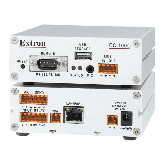
CC 100C Front and Rear Panel Connectors
Front Panel Connections
Front Panel
REMOTE
REMOTE
RESET
RESET
STATUS
STATUS
RS-232/485
RS-232/RS-485
A
B C D
1
Figure 1.
Front Panel Features and Connectors
Front panel connectors and features are listed below:
Reset Button — Press this reset button once to
A
remove the configuration password and reset the
unit to factory settings, with the exception of the
network configuration settings. To completely
reset the unit to factory defaults, including the
network configuration settings, press and hold
the reset button for 10 seconds and then release.
Status LEDs — These LEDs indicate power
B
and activity status of the unit. The left LED lights
green when power is present, and the right LED
flashes red with unit activity.
Mic Input — Insert a 3.5 mm connector into this
C
microphone input (TRS) audio jack.
Audio received on this input may be encoded
and streamed over the
network. Wire the TRS
connector as:
tip = microphone,
ring = power,
sleeve = ground.
Line In — Connect an unbalanced, line level,
D
mono audio input to this 2-pole connector.
Audio received on this input, when selected, is
encoded and streamed across the network.
Line Out — This 2-pole connector outputs
E
unbalanced, line level, mono audio. Connect this
port to the Extron PoleVault or VoiceLift auxiliary
input to amplify the audio for playback through
the system speakers.
Extron Safety and Regulatory Compliance
CC 100C
CC 100C
USB
USB
STORAGE
STORAGE
LINE
LINE
IN
IN
OUT
OUT
SUB
MIC
MIC
A B
3
4
5
E
6
Tip (Mic)
Ring
(Power)
Sleeve (Gnd)
3.5 mm Microphone Input Plug
Rear Panel Connections
F G
9
8
MIC
MIC
SPKR
SPKR
LAN/PoE
LAN/PoE
V
V
INPUT
RELAY
N/A
N/A
INPUT
RELAY
0
1 G NO C NC
1
2 G NO C NC
10
H
I
12
J
11
Figure 2.
Rear Panel Connectors
Rear panel connectors are listed below:
Mic Input — Microphone audio input is carried on this
F
3-pole connection. Input is encoded and streamed
over the network.
Speaker output (2 watt, mono) — For speaker
G
output, connect a mono speaker to this 2-pole
captive screw connector (see
on page 2 for wiring details).
Configurable Input: Contact —
H
Connect to this 3-pole captive
screw connection for contact
input. When triggered the contact input initiates audio
encoding for streaming over the network. Connect
port 0 or 1 to ground (G) to trigger the port.
Configurable Input: Relay —
I
Connect to this 3-pole captive
screw connection for relay
input. The connector has a
normally open relay (NO), a
common (C), and a normally
closed relay (NC).
LAN/PoE — For networking use, connect the LAN to
J
this RJ-45 connector. This port supports Power Over
Ethernet standard up to 48 V. The two associated
LEDs indicate connection and data activity. An
optional Extron PS PoE power injector can be used.
Power In — If not using PoE, connect a power supply
K
to the 2-pole captive screw connector or to the coaxial
connector for 12 V to 15 V power input. Observe the
correct polarity.
Rear Panel
POWER IN
POWER IN
12-15V
12-15V
12W MAX
12W MAX
K
Cabling the CC 100C
INPUT
RELAY
RELAY
0
1 G NO C NC
NO C NC
Normally
Normally
Open
Closed
INPUT
INPUT
RELAY
RELAY
0
0
1 G NO C NC
1 G
1
Advertisement
Table of Contents

Subscribe to Our Youtube Channel
Related Manuals for Extron electronics CC 100C

Summary of Contents for Extron electronics CC 100C
- Page 1 CC 100C • Installation Guide The Extron® CC 100C is an IP intercom public address and paging device, for use in Extron classroom AV systems and facilities, using the Extron Global Viewer Campus Communication Suite (GVCCS) software. Extron Safety and Regulatory Compliance...
- Page 2 CC 100C • Installation Guide (Continued) Cabling the CC 100C Connect the cables to the device as described below. Step 1 — Connect the LAN cable LAN/PoE connector (see figure on page 1)— Use a CAT 5e straight through network cable connect to a network.
- Page 3 After a restart, the procedure must be repeated. Either use a network cable to link the CC 100C and the PC directly, or connect the CC 100C to the PC via your network switch and power the device. Make sure that you have a valid static IP address configured on your PC (for example 192.168.0.2).
- Page 4 • The product serial number can be found both on the serial label (located on the CC 100C device) and on the unit box label.
Need help?
Do you have a question about the CC 100C and is the answer not in the manual?
Questions and answers