Table of Contents
Advertisement
Quick Links
CONTACT LOCAL BUILDING OR FIRE OFFICIALS ABOUT RESTRICTIONS AND INSTALLATION INSPECTION REQUIREMENTS
IN THE AREA.
READ THIS ENTIRE MANUAL BEFORE INSTALLATION AND USE OF THIS WOOD INSERT. FAILURE TO FOLLOW THESE
INSTRUCTIONS COULD RESULT IN PROPERTY DAMAGE, BODILY INJURY OR EVEN DEATH.
READ AND KEEP THIS MANUAL FOR REFERENCE
Printed in Canada
BLUE RIDGE 300-I
INSERT
(ESW0009 Model)
Wood Insert
Owner's Manual
Part 2 of 2
INSTALLATION AND
OPERATION REQUIREMENTS
Safety tested according to
ULC S628, UL 1482 and
UL 737 by an accredited
US Environmental Protection
Agency phase II certified
wood insert compliant with
2020 cord wood standard.
laboratory.
EPA
< ≤
2.5
g/h
46323_IA
Advertisement
Table of Contents

Subscribe to Our Youtube Channel
Related Manuals for Englander BLUE RIDGE 300-I INSERT


Summary of Contents for Englander BLUE RIDGE 300-I INSERT
- Page 1 Wood Insert Owner's Manual Part 2 of 2 INSTALLATION AND OPERATION REQUIREMENTS BLUE RIDGE 300-I INSERT (ESW0009 Model) Safety tested according to ULC S628, UL 1482 and UL 737 by an accredited laboratory. US Environmental Protection Agency phase II certified wood insert compliant with 2020 cord wood standard.
- Page 2 It is also highly recommended to register the warranty online at https://www.englander-stoves.com/ca/en/warranty-registration Registering the warranty will help to quickly find the information needed on the unit.
- Page 3 CERTIFICATION PLATE...
-
Page 5: Table Of Contents
Optional Fire Screen Installation ..................23 Air Tubes and Baffle Installation ..................24 Log retainers installation .....................27 Removal Instructions ....................28 3.10 Exploded Diagram and Parts List ................29 ENGLANDER LIMITED LIFETIME WARRANTY ................. 32 Product Specification Manual - Blue Ridge 300-I Page 5... -
Page 6: General Information
1. General Information Performances Values are as measured per test method, except for the recommended heating area, firebox volume, maximum burn time and maximum heat output. Blue Ridge 300-I (ESW0009) Models Non catalytic Type of combustion Dry Cordwood Fuel Type 500 to 2,100 ft (47 to 195 m Recommended heating area (sq. -
Page 7: Specifications
Specifications 16 in (406 mm) east-west Recommended log length 20 in (508 mm) east-west Maximum log length 6 in (150 mm) Flue outlet diameter 6 in (150 mm) Recommended connector pipe diameter ULC S635, CAN/ULC-S640, UL 1777 Type of chimney 12 feet Minimum liner height Vermiculite... -
Page 8: Dimensions
Dimensions 28 1/2" 5" 15 3/4" 723mm 127mm 401mm 26 7/8" 683mm 13 1/2" 28 1/2" 723mm 342mm 26 7/8" 683mm 13 1/2" 5" 15 3/4" 342mm 127mm 401mm 6" 153mm 6" 28 1/2" 723mm 153mm 26 7/8" 683mm 13 1/2" 3/16"... - Page 9 526mm 22 1/8" 562mm 26 1/2" 672mm 3/16" 1/4" 4" 16 1/2" 9" 419mm 228mm 21" 17 1/2" 11 7/8" 533mm 444mm 303mm 14 3/8" 364mm 9 7/8" 51mm 2 1/8" 62mm ©2022, FABRICANT DE POÊLE INTERNATIONAL INC. TOUS DROITS RÉSE Figure 5 : Door Opening 3/16"...
-
Page 10: Epa Loading
EPA Loading The loading methods shown below are those that were used during emissions certification. 1.4.1 Air control The air control is located underneath the ash shelf. To open the air control, pull the air control handle completely (High). This will increase the burn rate. To close the air control, push the air control handle completely toward the insert (Low). -
Page 11: Clearances To Combustible Material
2. Clearances to Combustible Material When the insert is installed so that its surfaces are at or beyond the minimum clearances specified, combustible surfaces will not overheat under normal and even abnormal operating conditions. NO PART OF THE INSERT MAY BE LOCATED CLOSER TO THE COMBUSTIBLE THAN THE MINIMUM CLEARANCE FIGURES GIVEN. -
Page 12: Floor Protection
Floor Protection t is necessary to have a floor protection made of non-combustible materials that meets the measurements specified in the "Table 1 : Floor Protection" below. Table 1 : Floor Protection FLOOR PROTECTION Canada 18" (457 mm) 16" (406 mm) 8"... -
Page 13: R Value
2.2.2 Installation Raised of More Than 5" (127 mm) If the extension of the masonry hearth is raised at least 5" (127 mm) from the floor protection, a non- combustible material, without an R-value, must extend at least 16" (406 mm in USA) or 18" (457 mm in Canada) in front of the unit (B). - Page 14 MATERIAL CONDUCTIVITY (K) RESISTANCE (R) PER INCH PER INCH THICKNESS Ceramic tile 12.5 0.008 Concrete 1.050 0.950 Mineral wool insulation 0.320 3.120 Limestone 0.153 Ceramic board (Fibremax) 0.450 Horizontal still air (1/8" thick) 0.135 0,920** Exemple: Required floor protection R of 1.00. Proposed materials: four inches of brick and one inch of Durock®...
-
Page 15: Installing Options On Your Product And Replacing Parts
3. Installing Options on Your Product and Replacing Parts Replacement and Adjustment 3.1.1 Door Note: The images shown are for guidance only and may be different from your product, but the assembly remains the same. In order for the insert to burn at its best efficiency, the door must provide a perfect seal with the firebox. - Page 16 3.1.2 Door Alignment To align, open the door and loosen the pressures screws located on the lower and upper hinges of the door using a 3/32” Allen key to free the adjustable hinge rods. 3/32" Using a flat screwdriver, turn the adjustable hinge rods in the direction shown to adjust the doors.
-
Page 17: Mandatory Installation
3.1.3 Gasket It is important to replace the gasket with another having the same diameter and density to maintain a good seal. Remove the door and place it face-down on something soft like a cushion of rags or a piece of carpet. - Page 18 • Install the combustion chamber side bricks as shown below. Figure 10 : Install the Combustion Chamber Bricks Figure 11 : Combustion Chamber Bricks Layout • Once the insert is properly positioned in the fireplace opening, secure the pipe with the pipe connectors (B) and screws (C) provided.
-
Page 19: Blower And Ash Lip Installation
Blower and Ash Lip Installation Note: The images shown are for guidance only and may be different from your product, but the assembly remains the same. Install the ash lip on the insert with four Center the blower on the ash lip and push screws. -
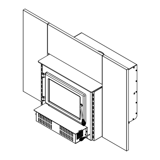
Page 20: Faceplate And Trims Installation
Faceplate and Trims Installation Note: The images shown are for guidance only and may be different from your product, but the assembly remains the same. Lay the panels on a flat and non abrasive surface. Align the top panel holes (A) with the left and right panels (B). - Page 21 Center the insert into the fireplace opening. Adjust its height using the leveling bolts on each side of the convection air jacket box until the faceplate is properly seated on the floor of the hearth extension. Then install one faceplate retainer spring on each side of the faceplate and attach the other end of the spring to the brackets on the left and right sides of the insert.
-
Page 22: Optional Fresh Air Intake Kit Installation
Optional Fresh Air Intake Kit Installation Note: The images shown are for guidance only and may be different from your product, but the assembly remains the same. The fresh air intake kit may be installed on the right or left end side of the unit. The unused side must be covered by the plate provided in the user manual kit. -
Page 23: Optional Fire Screen Installation
Optional Fire Screen Installation Note: The images shown are for guidance only and may be different from your product, but the assembly remains the same. In the United States or in provinces with a particulate emissions limit (e.g.: US EPA), the use of open-door wood stoves with a rigid firescreen is prohibited. -
Page 24: Air Tubes And Baffle Installation
Lean the upper part of the fire screen against the top door opening making sure to insert the top fire screen brackets behind the primary air deflector. Lift the fire screen upwards and push the bottom part towards the insert then let the fire screen rest on the bottom of the door opening. - Page 25 Align the notch in the left end of the tube with the key of the left air channel hole. Using a « Wise grip » hold the tube and lock it in place by turning the tube as shown. Make sure the notch reaches the end of the key way.
- Page 26 Page 26 Product Specification Manual - Blue Ridge 300-I...
-
Page 27: Log Retainers Installation
Log retainers installation 2" 2" Product Specification Manual - Blue Ridge 300-I Page 27... -
Page 28: Removal Instructions
Removal Instructions For inspecting purposes, the insert may need to be removed. To remove the insert, follow these instructions: • Remove the faceplate (D) by pulling it and releasing the springs holding it in place. • Remove the blower assembly (E). •... -
Page 29: Exploded Diagram And Parts List
3.10 Exploded Diagram and Parts List Product Specification Manual - Blue Ridge 300-I Page 29... - Page 30 IMPORTANT: THIS IS DATED INFORMATION. When requesting service or replacement parts for this unit, please provide the model number and the serial number. We reserve the right to change parts due to technology upgrades or availability. Contact an authorized dealer to obtain any of these parts.
- Page 31 Item Description 44028 CERAMIC THERMODISC F110-20F 44089 DOUBLE CAGE BLOWER 144 CFM 115V - 60Hz - 1.1A SE74193 INSERT BLOWER 30131 BLACK METAL SCREW #10 X 1/2" TYPE "A" PAN QUADREX 49028 5" WHITE AIR INTAKE TERMINATION Product Specification Manual - Blue Ridge 300-I Page 31...
-
Page 32: Englander Limited Lifetime Warranty
90 days *Subject to limitations above **Picture required Shall your unit or a components be defective, contact immediately your ENGLANDER dealer. To accelerate processing of your warranty claim, make sure to have on hand the following information when calling: •... - Page 34 Resale is strictly prohibited. The manufacturer may update St-Augustin-de-Desmaures (Québec) Canada this document from time to time and cannot be responsible G3A 2H3 for problems, injuries, or damages arising out of the use 1-877-356-6663 of information contained in any document obtained from https://www.englander-stoves.com/ unauthorized sources. tech@sbi-international.com...
Need help?
Do you have a question about the BLUE RIDGE 300-I INSERT and is the answer not in the manual?
Questions and answers