Table of Contents
Advertisement
Quick Links
BLUE RIDGE 150-I
(ESW0006 Model)
CONTACT LOCAL BUILDING OR FIRE OFFICIALS ABOUT RESTRICTIONS AND INSTALLATION INSPECTION REQUIREMENTS
IN THE AREA.
READ THIS ENTIRE MANUAL BEFORE INSTALLATION AND USE OF THIS WOOD INSERT. FAILURE TO FOLLOW THESE
INSTRUCTIONS COULD RESULT IN PROPERTY DAMAGE, BODILY INJURY OR EVEN DEATH.
READ AND KEEP THIS MANUAL FOR REFERENCE
Printed in Canada
21 7/8"
555mm
Wood Insert
Owner's Manual
Part 2 of 2
INSTALLATION AND
OPERATION REQUIREMENTS
Safety tested according to
ULC S628, UL 1482 and
UL 737 by an accredited
US Environmental Protection
Agency phase II certified
wood insert compliant with
2020 cord wood standard.
laboratory.
EPA
< ≤
2.5
g/h
46340_IA
Advertisement
Table of Contents

Related Manuals for Englander BLUE RIDGE 150-I


Summary of Contents for Englander BLUE RIDGE 150-I
- Page 1 Wood Insert Owner's Manual Part 2 of 2 INSTALLATION AND OPERATION REQUIREMENTS BLUE RIDGE 150-I (ESW0006 Model) Safety tested according to ULC S628, UL 1482 and UL 737 by an accredited laboratory. US Environmental Protection Agency phase II certified wood insert compliant with 2020 cord wood standard.
- Page 2 It is also highly recommended to register the warranty online at https://www.englander-stoves.com/ca/en/warranty-registration/ Registering the warranty will help to quickly find the information needed on the unit.
-
Page 3: Table Of Contents
Optional Fresh Air Intake Kit Installation...............27 4.10 Optional Fire Screen Installation ..................28 4.11 Air Tubes and Baffle Installation ..................29 4.12 Removal Instructions ....................32 4.13 Exploded Diagram and Parts List ................33 ENGLANDER LIMITED LIFETIME WARRANTY ................. 35 Product Specification Manual - Blue Ridge 150-I Page 3... -
Page 4: Certification Plate
1. Certification Plate Page 4 Product Specification Manual - Blue Ridge 150-I... -
Page 5: General Information
Tested and certified in compliance with CFR 40 part 60, subpart AAA, section 60.534(a)(1(ii) and ASTM E3053-17 based on the ALT-125 send by EPA on February 28 , 2018. Carbon monoxide. Product Specification Manual - Blue Ridge 150-I Page 5... -
Page 6: Specifications
MH standard. Tested and certified in compliance with CFR 40 part 60, subpart AAA, section 60.534(a)(1(ii) and ASTM E3053-17 based on the ALT-125 send by EPA on February 28 , 2018. Page 6 Product Specification Manual - Blue Ridge 150-I... -
Page 7: Dimensions
8 1/8" 207mm 17 3/8" 442mm 10 1/2" 2 1/4" 265mm 58mm 10 1/2" 2 1/4" 265mm 58mm Figure 2 : Front View Figure 3 : Side View - Maximum Insert Projection Product Specification Manual - Blue Ridge 150-I Page 7... - Page 8 19 1/4" 490mm 490mm Figure 5 : Top View - Combustion Chamber Figure 6 : Side View - Combustion Chamber BLUE RIDGE 150-I (ESW0006) Page 8 Product Specification Manual - Blue Ridge 150-I CHAMBRE À COMBUSTION/COMBUSTION CHAMBER BLUE RIDGE 150-I (ESW0006)
-
Page 9: Epa Loading Procedure
OFF to avoid blowing ash outside the combustion chamber. Refer to section "5.1 Blower" of the owner's manual for how to turn OFF the fan. Product Specification Manual - Blue Ridge 150-I Page 9... -
Page 10: Clearances To Combustible Material
15 ½" (394 mm) surround (H) If a fresh air intake is required, it is recommended to add at least 4" to the width of the minimum opening of the hearth. Page 10 Product Specification Manual - Blue Ridge 150-I... -
Page 11: Floor Protection
R value equal or greater than 1.00 and shall extend 23" (584 mm) in front of the unit. Information as reported by manufacturers and other resources. Product Specification Manual - Blue Ridge 150-I Page 11... - Page 12 K value = 0.75 Thickness = 1 R value = Thickness/K = 1/0.75 = 1.33 Horizontal still air can’t be «stack» to accumulate R-values; each layer must be separated with another non-combustible material. Page 12 Product Specification Manual - Blue Ridge 150-I...
-
Page 13: Installing Options On Your Product And Replacing Parts
Tuck any loose fibers under the gasket and into the silicone. Close the door. Do not use the insert for 24 hours. Product Specification Manual - Blue Ridge 150-I Page 13... - Page 14 Using a flat screwdriver, turn the adjustable hinge rods in the direction shown to adjust the doors. Tighten all door hinge pressure screws when they are at the desired positions. Configurations 1-2-3-4-5-6, show in which direction these act on the adjustment of the door. Page 14 Product Specification Manual - Blue Ridge 150-I...
- Page 15 Cut the gasket to the required length. Pinch the gasket onto the glass in a U shape, all around the glass. By following these instructions, the edge clearances are maintain. Product Specification Manual - Blue Ridge 150-I Page 15...
-
Page 16: Removal Of Refractory Stones
2. Unscrew the two supports (B) of the refractory bricks from the sides. The stones can then be removed in the order shown in Figure 12. 3/8" Figure 9 : Install the Combustion Chamber Bricks Figure 10 : Stones scheme Page 16 Product Specification Manual - Blue Ridge 150-I... -
Page 17: Connecting The Blower With A Bx Wire
(B) and gain access to the wires. Save the screws for later. 2. Disconnect the black (C) and white (D) wires. 3. Remove the ground screw (E) to remove the green wire. Save the screw for later. Product Specification Manual - Blue Ridge 150-I Page 17... - Page 18 5. Remove the piece of metal (G) from the plate (B) obstructing the hole to the left of the power cord (H) using pliers or a screwdriver. Cut the power cord (H) on each side of the black clamp. Page 18 Product Specification Manual - Blue Ridge 150-I...
- Page 19 9. Close the connection box by screwing in the plate (B) with the two screws (A) kept in step 1 and secure the BX wire by tightening the screw (L) of the connector (I). Product Specification Manual - Blue Ridge 150-I Page 19...
-
Page 20: Changing The Side Of The Blower Power Cord
Remove the four screws (F) that hold the connection box (G) to the insert and gently pull it out until the white and black wires come out of the insert. Keep the screws. Page 20 Product Specification Manual - Blue Ridge 150-I... - Page 21 Then pass the wires through the grommet (J) located on the side at the front of the device. 5. Screw the connection box (G) with the four screws (F) kept in step 2. Product Specification Manual - Blue Ridge 150-I Page 21...
- Page 22 (extension supplied with the manual kit). 8. Secure the excess wires using the three plastic grommets (C) removed in step 1. 9. Reinstall the grille (B) with the screws (A) kept in step 1. Page 22 Product Specification Manual - Blue Ridge 150-I...
-
Page 23: Blower Removal
DÉSINSTALLATION VENTILATEUR PT.1 enlever les annotations soous les détail et les lettre des détails 3. Unscrew the two wing nuts (C) on each side 4. Take out the fan (D). of the fan. Product Specification Manual - Blue Ridge 150-I Page 23... -
Page 24: Removable Air Control Handle
This insert comes with a removable handle for the primary air control. A holder for the handle is supplied with the manual. Here is an example of the holder installation. CAUTION: Do not leave the handle on the air control after use, as it will get very hot. Page 24 Product Specification Manual - Blue Ridge 150-I... -
Page 25: Faceplate Installation
(B) and (C). Secure together using the bolts (D) and nuts (E) provided. Install the grille on the assembled faceplate and bend the tabs using pliers. Hang the assembled faceplate on the insert. Product Specification Manual - Blue Ridge 150-I Page 25... -
Page 26: Faceplate Decorative Panel Installation/Removal
SI LE CLIENT VEUT INSTALLER SONT PRODUIT AVEC L'ENTONNOIR DETAIL I IL FAUT QU'IL INSTALLE LE RESTANT DES VIS (6X) Faceplate decorative panel installation • Screw the panel with 6 additional screws (B). Page 26 Product Specification Manual - Blue Ridge 150-I... -
Page 27: Optional Fresh Air Intake Kit Installation
Optional Fresh Air Intake Kit Installation The fresh air intake kit may be installed on the right or left end side of the unit. The unused side must be covered by the plate provided in the user manual kit. • Install the fresh air intake adapter (E) with four screws (F) then secure the flexible pipe (H) (not included) to the adapter using one of the pipe clamps (G). -
Page 28: Optional Fire Screen Installation
4.10 Optional Fire Screen Installation In the United States or in provinces with a particulate emissions limit (e.g.: US EPA), the use of open-door wood stoves with a rigid firescreen is prohibited. Open the door. Hold the fire screen by the two handles and bring it close to the door opening. -
Page 29: Air Tubes And Baffle Installation
Lean the upper part of the fire screen against the top door opening making sure to insert the top fire screen brackets in front of the primary air deflector. Lift the fire screen upwards and push the bottom part towards the insert then let the fire screen rest on the bottom of the door opening. - Page 30 Align the notch in the left end of the tube with the key of the left air channel hole. Using a « Wise grip » hold the tube and lock it in place by turning the tube as shown. Make sure the notch reaches the end of the key way.
-
Page 32: Removal Instructions
4.12 Removal Instructions For inspecting purposes, the insert may need to be removed. To remove the insert, follow these instructions: • Remove the blower grille (E) and faceplate (D) by lifting it and then pulling on it. • Remove the blower (C). •... -
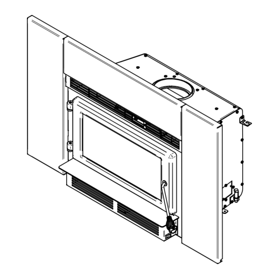
Page 33: Exploded Diagram And Parts List
4.13 Exploded Diagram and Parts List... - Page 34 PL74849 RIGHT FACEPLATE PL74847 TOP FACEPLATE PL74848 LEFT FACEPLATE SE46340 BLUE RIDGE 150-I MANUAL KIT AC05959 METALLIC BLACK STOVE PAINT - 342 g (12oz) AEROSOL SE74798 GLASS, GASKET AND MOULDING KIT SE74884 GLASS WITH GASKET 18 3/8'' X 9'' PL74798...
-
Page 35: Englander Limited Lifetime Warranty
90 days *Subject to limitations above **Picture required Shall your unit or a components be defective, contact immediately your ENGLANDER dealer. To accelerate processing of your warranty claim, make sure to have on hand the following information when calling: •... - Page 36 Resale is strictly prohibited. The manufacturer may update St-Augustin-de-Desmaures (Québec) Canada this document from time to time and cannot be responsible G3A 2H3 for problems, injuries, or damages arising out of the use 1-877-356-6663 of information contained in any document obtained from https://www.englander-stoves.com unauthorized sources. tech@sbi-international.com...
Need help?
Do you have a question about the BLUE RIDGE 150-I and is the answer not in the manual?
Questions and answers