Advertisement
Owner's Manual & Safety Instructions
Save This Manual
operating, inspection, maintenance and cleaning procedures. Write the product's serial number in the
back of the manual near the assembly diagram (or month and year of purchase if product has no number).
Keep this manual and the receipt in a safe and dry place for future reference.
email our technical support at: productsupport@harborfreight.com
When unpacking, make sure that the product is intact
and undamaged. If any parts are missing or broken,
please call 1-888-866-5797 as soon as possible.
©
Copyright
2022 by Harbor Freight Tools
No portion of this manual or any artwork contained herein may be reproduced in
any shape or form without the express written consent of Harbor Freight Tools.
Diagrams within this manual may not be drawn proportionally. Due to continuing
improvements, actual product may differ slightly from the product
described herein. Tools required for assembly and service may not be included.
Keep this manual for the safety warnings and precautions, assembly,
Visit our website at: http://www.harborfreight.com
®
. All rights reserved.
read this material before using this
product. Failure to do so can result in
serious injury. SaVe tHiS ManuaL.
22h
Advertisement

Related Manuals for CEN-TECH CM300


Summary of Contents for CEN-TECH CM300
- Page 1 Owner’s Manual & Safety Instructions Save This Manual Keep this manual for the safety warnings and precautions, assembly, operating, inspection, maintenance and cleaning procedures. Write the product’s serial number in the back of the manual near the assembly diagram (or month and year of purchase if product has no number). Keep this manual and the receipt in a safe and dry place for future reference.
-
Page 2: Table Of Contents
table of contents Safety ..........3 Operation ........8 Specifications ......5 Maintenance .......14 Setup ...........6 Warranty ........16 WarninG SyMBOLS anD DeFinitiOnS This is the safety alert symbol. It is used to alert you to potential personal injury hazards. Obey all safety messages that follow this symbol to avoid possible injury or death. -
Page 3: Safety
iMpOrtant SaFety inFOrMatiOn Safety Warnings and precautions read all safety warnings and all instructions. Failure to follow the warnings and instructions may result in electric shock, fire and/or serious injury. Save all warnings and instructions for future reference. Electrical shock can cause death Use caution when working near or injury! NEVER TOUCH exposed voltages above 30 VAC rms, 42 VAC... - Page 4 15. People with pacemakers should 21. The warnings, cautions, and consult their physician(s) before instructions discussed in this instruction use. Electromagnetic fields in close manual cannot cover all possible proximity to heart pacemaker could conditions and situations that may cause pacemaker interference occur.
-
Page 5: Specifications
Specifications Function range resolution accuracy AC Voltage 600V 0.1V ±(1.2% + 3 digits) DC Voltage 600mV 0.1mV ±(0.7% + 3 digits) 6000mV ±(0.5% + 2 digits) 0.01V ±(0.7% + 3 digits) 600V 0.1V ±(0.7% + 3 digits) DC Current 600uA, 60mA, 600mA 0.1µA, 0.01mA, ±(1.0% + 3 digits) 0.1mA... -
Page 6: Setup
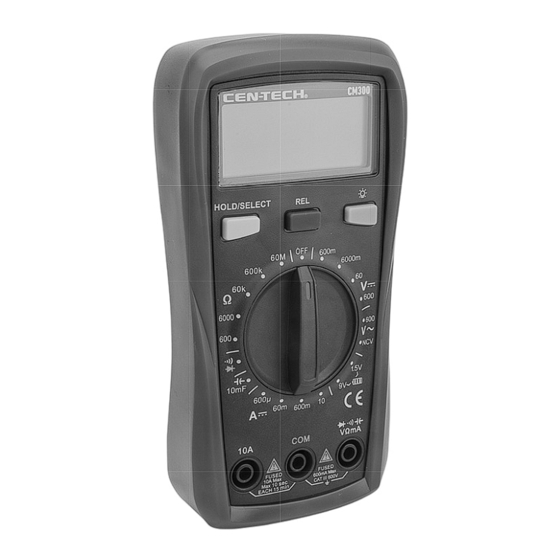
Setup - Before use: read the entire iMpOrtant SaFety inFOrMatiOn section at the beginning of this manual including all text under subheadings therein before set up or use of this product. Functions LcD Display Back Light Button Hold/Select Button relative Button rotary Dial VΩma input terminal... - Page 7 Display Symbol Description Auto Power Off Dangerous Voltage Levels Data Hold Mode Direct Current Minus Sign Alternating Current Non Contact Voltage Diode Test Audible Continuity Good Low Bad Battery Measurement Low Battery 6000 count LcD Display 0 to 5999 measurement Reading mV, V Volts (Voltage) μa, ma, a...
-
Page 8: Operation
Operating instructions read the entire iMpOrtant SaFety inFOrMatiOn section at the beginning of this manual including all text under subheadings therein before set up or use of this product. electrical shock can cause death or injury! neVer tOucH exposed conductors of electricity. - Page 9 Measurement Operation note: Remove plugs from Buzzer notification: ends of Test Leads (included) Input voltage >600V (AC/DC), buzzer before connecting to Meter. will continuously beep indicating note: Test Lead probes have removable measure range is at limit. covers for overvoltage protection. With Input current >10A (AC/DC), buzzer covers in place, Test Leads are rated for will continuously beep indicating...
- Page 10 Dc Voltage Measurement Measure DC conductors Turn Rotary Dial to the (DCV) carrying up to 600 VDC. position to choose DC voltage. WarninG! tO preVent SeriOuS Carefully touch exposed inJury: Use caution when working conductors with tips of probes. near voltages above 30 VAC rms, 42 Read measured voltage on the Display.
- Page 11 continuity Measurement Test continuity between two Connect the test leads across points of a circuit. the circuit to be measured. WarninG! tO preVent SeriOuS Read measured resistance on the inJury: To prevent electric shock, turn off Display. If measured resistance is less all power and fully discharge capacitors on than 30Ω...
- Page 12 capacitance Measurement Measure capacitors to indicate the Turn Rotary Dial to the amount of energy they can store. (capacitance) position. WarninG! tO preVent SeriOuS Read the measured capacitance inJury: To prevent electric shock, turn off value on the Display. all power and fully discharge capacitors on note: 10mF capacitors can take up to the circuit under test before measuring.
- Page 13 Battery Measurement note: Only measure 1.5V or 9V Connect red probe to the battery’s batteries. Measuring batteries over anode and black probe to its cathode. 9 Volts can damage the meter. Reading is displayed: Turn the Rotary Dial to the •...
-
Page 14: Maintenance
Maintenance and Servicing procedures not specifically explained in this manual must be performed only by a qualified technician. cleaning, Maintenance, and Lubrication Wipe unit with a dry, lint-free cloth. Other than the batteries, there Do not use solvents or abrasives. are no replaceable parts on this unit. - Page 15 Battery replacement If the symbol appears on the LCD Remove screw on battery cover. display, the battery should be replaced. Remove battery cover carefully. Remove Test Leads from the Meter. Pull batteries out of unit and Turn the unit over. replace with the same.
-
Page 16: Warranty
Limited 90 Day Warranty Harbor Freight Tools Co. makes every effort to assure that its products meet high quality and durability standards, and warrants to the original purchaser that this product is free from defects in materials and workmanship for the period of 90 days from the date of purchase. This warranty does not apply to damage due directly or indirectly, to misuse, abuse, negligence or accidents, repairs or alterations outside our facilities, criminal activity, improper installation, normal wear and tear, or to lack of maintenance.
Need help?
Do you have a question about the CM300 and is the answer not in the manual?
Questions and answers
how to replace fuses on the CM300
To replace fuses on the CEN-TECH CM300:
1. Turn off the meter and remove the test leads.
2. Turn the unit over and remove the protective case.
3. Open the meter to access the internal components.
4. Locate the two ceramic fuses (one for low current and one for high current).
5. Carefully remove the blown fuse(s).
6. Replace with the same type and rating ceramic fuse(s).
7. Reassemble the meter and replace the protective case.
This answer is automatically generated
how in the world do you install the provided batteries? i just purchased the meter
To install batteries in the CEN-TECH CM300 meter:
1. Remove the test leads from the meter.
2. Turn the unit over.
3. Remove the protective case.
4. Remove the screw on the battery cover.
5. Carefully remove the battery cover.
6. Insert the batteries (same type as required).
7. Replace the cover and retighten the screw.
This answer is automatically generated
How do you put batteries in the meter
How to put batteries in cm300
How do you install battery
What settings on dial and which plug in for leads in testing a thermostat for power
Will the cm300 test house ac current?young