Sign In
Upload
Download
Table of Contents
Contents
Add to my manuals
Delete from my manuals
Share
URL of this page:
HTML Link:
Bookmark this page
Add
Manual will be automatically added to "My Manuals"
Print this page
×
Bookmark added
×
Added to my manuals
Manuals
Brands
Argox Manuals
Printer
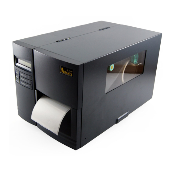
X-2300
Technical manual
Argox X-2300 Series Technical Manual
Hide thumbs
Also See for X-2300 Series
:
User manual
(126 pages)
1
Table Of Contents
2
3
4
5
6
7
8
9
10
11
12
13
14
15
16
17
18
19
20
21
22
23
24
25
26
27
28
29
30
31
32
33
34
35
36
37
38
39
40
41
42
43
44
45
46
47
48
49
50
51
52
53
54
55
56
57
58
59
60
61
62
63
64
65
66
67
68
69
70
71
72
73
74
75
76
77
page
of
77
Go
/
77
Contents
Table of Contents
Troubleshooting
Bookmarks
Table of Contents
Table of Contents
General Introduction
Scope
Printer Description
Related Manuals
Printer Specification
Printing
Media and Ribbon
Fonts
Bar Code
Graphic
Electrical and Operating Environment
Physical Dimension
Agency List
Communication
Controls and Indicators
Front Panel
LCD Setting
Rear Panel
Options
Cutter Mechanism
Dispenser and Rewinder
Super (Add-On) Card
External Media Stacker
Argox Scanner
Argokee
SETUP and DIAGNOSITC
Inlet Power Voltage and Grounding
Perform the Self Test
Perform the Curves
Printer Reset
Calibration and Adjustments
Media Sensor Position Adjustment
Media Sensor Calibration
Print Head Pressure Adjustment
Print Head Print Line Adjustment
Ribbon Tension Adjustment
Printing Wrinkle Adjustment
Optional Parts Installations
Cutter Installation
Dispenser/Rewinder Installation and Adjustment
Firmware Upgrading
Upgrade Firmware in Normal Case
How to Transferring Emulation
Upgrade Firmware in Crashed Case
Verification
Maintenance and Trouble Shooting
Printer Status Indication
Trouble Shooting
Clearance
Replacement
Cutter with Paper Jam
Operational Theorem
System Block Diagram
Main Board Block Diagram and Description
Panel Board Block Diagram and Description
Sensor Board Diagram and Description
Wiring Diagram
Advertisement
Quick Links
1
Calibration and Adjustments
Download this manual
X-2300/X-3200 Series
Technical Manual
Rev.1.05
Table of
Contents
Previous
Page
Next
Page
1
2
3
4
5
Advertisement
Table of Contents
Troubleshooting
MAINTENANCE AND TROUBLE SHOOTING
56
Trouble Shooting
58
Need help?
Do you have a question about the X-2300 Series and is the answer not in the manual?
Ask a question
Questions and answers
Related Manuals for Argox X-2300 Series
Barcode Reader Argox X-2300 User Manual
(126 pages)
Printer Argox Argox X-1000VL User Manual
Xellent series industrial barcode printer (63 pages)
Printer Argox OS-2130DE User Manual
Ethernet printer (51 pages)
Printer Argox X2000 User Manual
Barcode printer (38 pages)
Printer Argox X-3200 Series Technical Manual
(77 pages)
Printer Argox CP-2140Z User Manual
Compact printer (82 pages)
Printer Argox D4 250 User Manual
D4 series printer (65 pages)
Printer Argox P4 Series User Manual
(75 pages)
Printer Argox R-400plus User Manual
Refine series (72 pages)
Printer Argox MP Series User Manual
(80 pages)
Printer Argox iX4 Series User Manual
(92 pages)
Printer Argox OS Series Manual
(69 pages)
Printer Argox A-2240 User Manual
A series (47 pages)
Printer Argox CP-2140 User Manual
Compact printer series (84 pages)
Printer Argox CP-Series Quick Installation Manual
(4 pages)
Printer Argox A-50 Manual
(34 pages)
This manual is also suitable for:
X-3200 series
Table of Contents
Print
Rename the bookmark
Delete bookmark?
Delete from my manuals?
Login
Sign In
OR
Sign in with Facebook
Sign in with Google
Upload manual
Upload from disk
Upload from URL


Need help?
Do you have a question about the X-2300 Series and is the answer not in the manual?
Questions and answers