Table of Contents
Advertisement
Quick Links
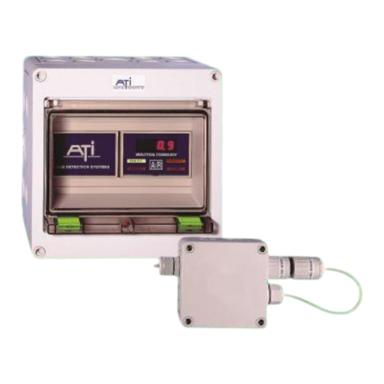
Formaldehyde Gas Monitor
Home Office
Analytical Technology, Inc.
6 Iron Bridge Drive
Collegeville, PA 19426
Phone: 800-959-0299
610-917-0991
Fax:
610-917-0992
Email: sales@analyticaltechnology.com
Web: www.Analyticaltechnology.com
8Fax: 610-917-0992
O & M Manual
GasSens
Fax:
+ 44 (0)1457-874-468
European Office
ATI (UK) Limited
Unit 1 & 2 Gatehead Business Park
Delph New Road, Delph
Saddleworth OL3 5DE
Phone: +44 (0)1457-873-318
Fax:
+ 44 (0)1457-874-468
Email: sales@atiuk.com
Advertisement
Table of Contents

Subscribe to Our Youtube Channel
Related Manuals for ATI Technologies GasSens A14


Summary of Contents for ATI Technologies GasSens A14
- Page 1 O & M Manual GasSens Formaldehyde Gas Monitor Home Office European Office Analytical Technology, Inc. ATI (UK) Limited 6 Iron Bridge Drive Unit 1 & 2 Gatehead Business Park Collegeville, PA 19426 Delph New Road, Delph Phone: 800-959-0299 Saddleworth OL3 5DE 610-917-0991 Phone: +44 (0)1457-873-318 Fax:...
-
Page 2: Table Of Contents
GasSens Gas Detection System Section 1 - Overview TABLE OF CONTENTS TABLE OF CONTENTS ............................ 1 INTRODUCTION ............................1-3 A11 S ..........................1-4 ENSOR RANSMITTER A14 R ..........................1-4 ECEIVER ODULE A17 P ......................... 1-4 OWER UPPLY ODULE NEMA 4X E .......................... - Page 3 GasSens Gas Detection System Section 1 - Overview BATTERY BACKUP PARTS LIST ....................... 4-3 STROBE PARTS LIST ............................ 4-3 STROBE LIGHT ............................. 4-3 O & M Manual A14-RK, 8/06 1 - 2...
-
Page 4: Introduction
GasSens Gas Detection System Section 1 - Overview INTRODUCTION GasSens is an on-line monitoring system for the detection of hazardous gases in ambient air. It is designed to detect and alarm gas leaks from storage cylinders, process piping, or gas feed equipment in virtually any type of industrial plant environment. -
Page 5: A11 Sensor/Transmitter
GasSens Gas Detection System Section 1 - Overview A11 Sensor/Transmitter Consists of an electrochemical gas sensor closely coupled to a NEMA 4X transmitter. This component measures gas concentration and converts the measurement to a digital signal for transmission to a receiver module. It must be mounted in the area where gas leakage or buildup is expected, and can either be wall mounted or supported by electrical conduit carrying interconnecting wiring. -
Page 6: Audible Horn
GasSens Gas Detection System Section 1 - Overview Audible Horn A 12 VDC piezoelectric alarm horn is available for mounting into any of the NEMA 4X enclosures. The horn is wired to the receiver module and will sound intermittently when the warning setpoint is reached, and continuously when the alarm setpoint is reached. -
Page 7: Mechanical Installation
GasSens Gas Detection System Section 1 - Overview MECHANICAL INSTALLATION System enclosures, battery back-up units, and sensor transmitters are all designed for surface mounting using screws or bolts inserted through the recessed mounting holes at each corner of the enclosures. Included with each system enclosure is a template with mounting hole dimensions for two and three module system enclosures, battery back-up enclosure, and sensor/transmitter enclosure. - Page 8 GasSens Gas Detection System Section 1 - Overview For installations where conduit will not be used, cable gland seal fittings must be installed in the conduit hubs. Plastic cable glands are available from most electrical supply stores. Gland seals with 1/2" NPT threads will screw directly into the conduit hub. Gland seals are also available from ATI for installation directly into the enclosures in place of the conduit hubs.
- Page 9 GasSens Gas Detection System Section 1 - Overview FRONT VIEW SIDE VIEW THRU HOLES FOR SURFACE MOUNTING (4) #6 SCREWS BOTTOM VIEW Figure 1-2: Two Module System Enclosure Dimensions (80-0006R) O & M Manual A14-RK, 8/06 1 - 8...
- Page 10 GasSens Gas Detection System Section 1 - Overview FRONT VIEW SIDE VIEW THRU HOLES FOR SURFACE MOUNTING (4) #6 SCREWS BOTTOM VIEW Figure 1-3: Three Module System Enclosure Dimensions (80-0007R) O & M Manual A14-RK, 8/06 1 - 9...
- Page 11 GasSens Gas Detection System Section 1 - Overview Figure 1-4: Six Module System Enclosure Dimensions (80-0008R) O & M Manual A14-RK, 8/06 1 - 10...
-
Page 12: Electrical Installation
GasSens Gas Detection System Section 1 - Overview ELECTRICAL INSTALLATION Field wiring required for a detection system includes connection of AC power, connection of two conductor cable between the receiver and the sensor/transmitter, and connection of the battery back-up unit if it was purchased with the system. ATI does not supply an AC power cord with the system. - Page 13 GasSens Gas Detection System Section 1 - Overview Two point detectors include one power supply and two receivers. These systems are shipped factory wired as shown in Figure 1-6 below. Analytical Technology, Inc. Figure 1-6: Dual Point Receiver Internal Wiring, (ATI-033) O &...
- Page 14 GasSens Gas Detection System Section 1 - Overview Analytical Technology, Inc. Analytical Technology, Inc. Figure 1-7: Four Point Receiver Internal Wiring (ATI-075) O & M Manual A14-RK, 8/06 1 - 13...
- Page 15 GasSens Gas Detection System Section 1 - Overview Multipoint systems supplied in “Large” type enclosures use a 65 watt power supply located in the top of the enclosure. This power supply is designed to power up to 12 of the A14 receiver modules.
- Page 16 GasSens Gas Detection System Section 1 - Overview Sensor/transmitters contain two 2-position terminal blocks, one for receiver connection and one for connection of the Auto-Test generator. Connection of the two wires from the receiver are not polarity sensitive. These wires can be hooked up without regard to terminal position. Connection of the generator is polarity sensitive.
- Page 17 GasSens Gas Detection System Section 1 - Overview Analytical Technology, Inc. Figure 1-10: Typical System Wiring, Explosion-proof Transmitter Version (ATI-076) The remainder of this manual is divided into sections that describe each component of the system. Mechanical and electrical installation are the only requirements to provide a workable system.
-
Page 18: Receiver Module
GasSens Gas Detection System Section 2 - A14 Receiver Module RECEIVER MODULE Introduction Series A14 Receivers provide the user interface to the gas detection system. Each receiver is connected to a series A11 sensor/transmitter with a 2 conductor cable, and displays information on the gas concentration in the sensor area. - Page 19 GasSens Gas Detection System Section 2 - A14 Receiver Module TROUBLE 1: +12 Module Power positive (12 VDC) 1: A1 NO Alarm 1 normally open contact 2: C Module Power Common 2: A1 C Alarm 1 common 3: Earth Ground (REQUIRED) 3: A1 NC Alarm 1 normally closed contact 4: H+ Audible Horn positive 4: A2 NO Alarm 2 normally open contact...
-
Page 20: Factory Configuration
GasSens Gas Detection System Section 2 - A14 Receiver Module Factory Configuration All receivers are identical except for the gas symbol attached to the green power LED. Operating range, alarm relay configuration, display intensity, and Auto-Test activation are selectable using 4 banks of DIP switches located on the configuration circuit board inside the module. - Page 21 GasSens Gas Detection System Section 2 - A14 Receiver Module Figure 2-4: Configuration Switch Functions (0110PM) O & M Manual A14-RK, 8/06 2 - 4...
-
Page 22: Setpoint Selection
GasSens Gas Detection System Section 2 - A14 Receiver Module Setpoint Selection The operating range and the Warning and Alarm setpoints can be changed, if desired, by using the configuration switches identified in Figure 2-4. The Warning setpoint is set using switches A2-A8 and the Alarm setpoint is set using switches B2-B8. -
Page 23: Range Selection
GasSens Gas Detection System Section 2 - A14 Receiver Module Range Selection Display range selection is made using binary numbers to represent the full scale operating range for the receiver. Table 2-2 provides the proper switch settings for the ranges available on each receiver. -
Page 24: External Horn Relay
GasSens Gas Detection System Section 2 - A14 Receiver Module Relays may be configured for either Fail-safe or Normal operation. The designation of normal or fail-safe refers to the operation of the relay coil during normal operation. A relay configured for Normal operation will have the relay coil energized when an alarm occurs and de-energized during normal operation. -
Page 25: Operation
GasSens Gas Detection System Section 2 - A14 Receiver Module OPERATION Startup Receiver front panels contain four LED bar indicators and a 4 digit LED display. The digital display indicates gas concentration in either PPM, PPB, or percent. The green LED bar is marked with the gas symbol and units of measurement (PPM, PPB, or %) specified on the customer order. -
Page 26: Trouble Alarm And Relay
GasSens Gas Detection System Section 2 - A14 Receiver Module Trouble Alarm and Relay Receivers contain a TROUBLE indicator and an associated SPDT relay. The trouble alarm will be activated if the transmitter cable is broken or shorted, or if electronic component failure in either the transmitter or receiver causes a loss of digital input. -
Page 27: Lamp And Horn Test
GasSens Gas Detection System Section 2 - A14 Receiver Module When the Auto-Test is activated, the generator will turn on for a maximum of 5 minutes. If no sensor response is detected during this time, the generator will turn off and the receiver will wait for 15 minutes before initiating another Auto-Test. -
Page 28: Manual Auto-Test
GasSens Gas Detection System Section 2 - A14 Receiver Module Manual Auto-Test Gas detection systems purchased with the optional Auto-Test generator may be tested by manual activation of the generator from the receiver module. This function will operate only if the Auto-Test configuration switch D1 is 'on'. -
Page 29: Auto-Test Remote Verification
GasSens Gas Detection System Section 2 - A14 Receiver Module Auto-Test Remote Verification A14 Receiver modules with a software revision G or higher use the analog output to indicate that a successful Auto-Test has occurred. This allows a recording device to show evidence of the successful test. -
Page 30: Troubleshooting
GasSens Gas Detection System Section 2 - A14 Receiver Module TROUBLESHOOTING Receiver modules will normally provide trouble free operation over many years of service. However, should problems arise, a few simple tests can be done to determine if the receiver is functioning properly. -
Page 31: Receiver Module Parts List
GasSens Gas Detection System Section 2 - A14 Receiver Module RECEIVER MODULE PARTS LIST TOP HALF OF ENCLOSURE (80-0002) PLUG-ON TERMINAL BLOCK (38-0006) BOTTOM HALF OF ENCLOSURE (80-0002) PC BOARD ASSEMLBY FRONT PANEL (34-0009) PLUG-ON TERMINAL BLOCK (38-0009) Part Number Description 00-0056 Complete receiver module (Specify Gas) -
Page 32: A17 Universal Power Supply
Universal Power Supply Section 3 – A17 Power Supply Module A17 UNIVERSAL POWER SUPPLY The power supply module used in the GasSens system (part #00-0055) is a self-adjusting supply that will accept the AC power provided in virtually every country in the world. Any AC (50-60 Hz.) or DC voltage from 85 volts to 270 volts can be connected to the power input terminals on TB4. - Page 33 Universal Power Supply Section 3 – A17 Power Supply Module Figure 3-1 provides detailed information on the terminals provided on the power supply. All terminal blocks are plug-in type, and can be easily unplugged should removal of the module be necessary. Analytical Technology, Inc.
-
Page 34: Power Supply Parts List
Universal Power Supply Section 3 – A17 Power Supply Module POWER SUPPLY PARTS LIST Part Number Description 00-0055 Complete power supply module 81-0064 Module enclosure (top and bottom) 34-0011 Front overlay 38-0065 AC power terminal block plug, 3 position 38-0066 Power failure relay &... -
Page 35: Optional Equipment
GasSens Gas Detection System Section 4 - Optional Equipment OPTIONAL EQUIPMENT Battery back-up units for GasSens detection systems (part #00-0057) are separate components housed in a NEMA 4X wall mount enclosure. Back-up units include a 4 ampere-hour sealed lead acid battery with a control circuit attached to the battery terminals. -
Page 36: Operation
GasSens Gas Detection System Section 4 - Optional Equipment Electrical connection is made between the battery back-up unit and the power supply module. The circuit board mounted on the battery contains a 2 position plug-in terminal block marked plus and minus. The plus terminal is connected to terminal B+ of the power supply and the minus terminal is connected to B- of the power supply. - Page 37 GasSens Gas Detection System Section 4 - Optional Equipment BATTERY BACKUP PARTS LIST Part Number Description 00-0057 Complete battery back-up unit 01-0011 Battery back-up circuit board 80-0009 NEMA 4X enclosure (top and bottom) 48-0010 Battery bracket 29-0002 Battery, 12 V, 4 A-H 92-0022 Self-tapping screws, (Pkg.
- Page 38 GasSens Gas Detection System Section 4 - Optional Equipment STROBE LIGHT The accessory alarm indicating strobe light (part number 35-0002) available for use with the GasSens alarm system is a weatherproof high-intensity strobe operating from a 12 VDC power source. The strobe can be conveniently mounted on the top or either side of the alarm enclosure using one of the 1/2"...
- Page 39 GasSens Gas Detection System Section 5 - A11-38 HCOH Sensor/Transmitter INTRODUCTION Series A11 sensor/transmitters combine electrochemical gas sensors and an electronic amplifier that transmits gas concentration using a current pulse position technique. When ordered as an option, sensor/transmitters are also supplied with a gas generator that provides the Auto-Test automatic sensor testing system.
- Page 40 GasSens Gas Detection System Section 5 - A11-38 HCOH Sensor/Transmitter Notes: 1) Enclosure Ratings: Nema-4X/IP 66. 2) Enclosure Material: Polystyrene, standard gray 3) Knockouts: Pg 11 (.75” dia.) Pg 16 (.90” dia.) 4) **These are the dimensions between knockouts and are typical for (3) sides with (2) knockouts each.
- Page 41 GasSens Gas Detection System Section 5 - A11-38 HCOH Sensor/Transmitter Figure 5-2: Explosion-Proof Sensor/Transmitter Dimensions (ATI-046, ATI-0170) __________________________________________________________________________________ O & M Manual Rev-C, 11/09...
- Page 42 GasSens Gas Detection System Section 5 - A11-38 HCOH Sensor/Transmitter SENSOR LOCATION Formaldehyde gas is heavier than air and will tend to accumulate near the floor in a closed room with little air movement. If there is good air circulation in an enclosed area, some chlorine will undoubtedly be carried throughout the area.
- Page 43 GasSens Gas Detection System Section 5 - A11-38 HCOH Sensor/Transmitter NOTE: If alarm relays at the receiver are connected to devices that should not be activated during calibration, place the receiver into 'alarm inhibit' as described in the Section 2 of this manual prior to calibrating the sensor/transmitter.
- Page 44 GasSens Gas Detection System Section 5 - A11-38 HCOH Sensor/Transmitter If a formaldehyde standard of another value is being used, or if the transmitter range is not the standard 0-20 PPM, calculate the calibration voltage using the following formula. V = Interference Factor X (Span Gas Concentration ÷ Transmitter Range) As an example, if your span gas cylinder is marked with a concentration of 40 PPM CO as a surrogate and it is used to calibrate a 0-20 PPM sensor/transmitter, the calculation would be: V = 0.30 X (40 ÷...
- Page 45 GasSens Gas Detection System Section 5 - A11-38 HCOH Sensor/Transmitter SENSOR RESPONSE TEST While zero and span adjustments are required only periodically, gas sensors should be checked regularly for proper response. The response check can be done quickly by simply aiming the outlet tube from a CO cylinder at the face of the sensor and turning on the gas flow for 10-20 seconds.
- Page 46 GasSens Gas Detection System Section 5 - A11-38 HCOH Sensor/Transmitter FORMALDEHYDE NEMA-4X SENSOR/TRANSMITTER PARTS LIST Part Number Description 00-1049 Complete Formaldehyde sensor/transmitter assembly 00-1045 A10-38 Gas Sensor 01-0138 A11-38 Transmitter circuit board 81-0002 NEMA 4X enclosure (top and bottom) 92-0005 Self-tapping screw (Pkg.
- Page 47 GasSens Gas Detection System Section 5 - A11-38 HCOH Sensor/Transmitter FORMALDEHYDE EXPLOSION-PROOF SENSOR/TRANSMITTER PARTS LIST Part Number Description 00-1051 Complete Formaldehyde sensor/transmitter assembly-XP 00-1053 C10-38 Formaldehyde gas sensor 03-0039 Explosion-proof enclosure assembly 92-0007 Self-tapping screws (Pkg. Of 4) 38-0002 Terminal block plug, 2 position __________________________________________________________________________________ O &...
- Page 48 PRODUCT WARRANTY Analytical Technology, Inc. (Manufacturer) warrants to the Customer that if any part(s) of the Manufacturer's equipment proves to be defective in materials or workmanship within the earlier of 18 months of the date of shipment or 12 months of the date of start- up, such defective parts will be repaired or replaced free of charge.
- Page 49 WATER QUALITY MONITORS GAS DETECTION PRODUCTS Dissolved Oxygen Ammonia Carbon Monoxide Free Chlorine Hydrogen Combined Chlorine Nitric Oxide Total Chlorine Oxygen Residual Chlorine Dioxide Cl2 Phosgene Potassium Permanganate Bromine Chlorine Dissolved Ozone Chlorine Dioxide pH/ORP Fluorine Conductivity Iodine Hydrogen Peroxide Acid Gases Peracetic Acid O Ethylene Oxide...
Need help?
Do you have a question about the GasSens A14 and is the answer not in the manual?
Questions and answers