Table of Contents
Advertisement
Quick Links
Advertisement
Table of Contents

Subscribe to Our Youtube Channel
Summary of Contents for KROM 21
- Page 1 OWNER’S MANUAL KROM Model 21...
-
Page 2: Table Of Contents
3.3 Optical sensor ..........................6 3.4 Power supply ..........................6 3.5 USB-cable ............................ 6 3.6 KROM application ........................6 4 The KROM application ........................6 4.1 Unit tab ............................7 4.2 Measurement tab .......................... 7 4.3 Analysis tab ..........................9 4.3.1 Absolute values ........................ -
Page 3: Introduction
1 Introduction With the KROM system from Genmag AB you can measure the magnetic flux density in the airgap of synchronous generators and motors at full speed. Measurements should be performed at reduced field current to avoid magnetic saturation of the steel. Stator currents will also affect the measurement. -
Page 4: Top
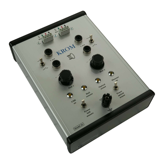
3.1.1 Top Controls and indicators are located on the upper side of the instrument. Table 1. Content of instrument top side. Item Description Ground terminal Power switch for Hall sensors Power switch for optical Power indicator for USB Power indicator for Hall sensors Power indicator for the optical sensor Indicator for ongoing measurement Supply current adjustment for Hall sensors... -
Page 5: Back
3.1.2 Back The contacts on the back of the instrument are listed in table 2. Table 2. Back panel contacts. Item Description USB contact for computer Contact for external 12 V power supply Contact for optical sensor... -
Page 6: Hall Sensors
4 The KROM application The KROM application consists of three tabs and a graph area. The information entered in the tabs Unit and Measurement is used in the plot you create in the tab Analysis. All information entered in the Unit... -
Page 7: Unit Tab
Date and time can not be modified. KROM is a data collection system but it also provides a way to monitor the signals before a measure- ment is started to verify the health of the sensors. - Page 8 Figure 2. A comment about the measure- ment can be entered in the second tab. Field voltage is entered here. Table 4. Input fields and buttons on the tab Measurement. Name Comment Comment to measurement – Text input field Specific information regarding this measurement, for example the field current or terminal voltage.
-
Page 9: Analysis Tab
sensor and Hall sensor 1 are displayed during monitoring. 4.3 Analysis tab The analysis tab provides several options for the analysis of your measurement. The default setting is to show the amplitude of the measured magnetic flux. 4.3.1 Absolute values The selection of this option causes the program to display the absolute value of the magnetic flux, showing negative flux as positive. - Page 10 Figure 3. Several options regarding the graphs are available in the Analysis tab.
-
Page 11: Preparing For Data Collection
Figure 4. A screenshot of the KROM application. The black graph is the signal from the optical sensor, indicating the position of pole one. 5 Preparing for data collection 5.1 Mounting the Hall sensor The Hall sensor shall be glued to a stator tooth. -
Page 12: Mounting The Optical Sensor
Figure 6. Sketch of how to mount a Hall sensor on a stator tooth. 5.2 Mounting the optical sensor The reflective tape should be mounted over pole number one and the optical sensor should be mounted in the same position as the Hall sensors, for example upstream. Reflective tape Shaft... -
Page 13: Adjusting The Supply Current To The Hall Sensors
Reflective tape Shaft Figure 8. Alternative mounting of the optical sensor. If reflections from the shaft is a problem it is also possible to position the optical sensor at an angle in the horizontal plane. Care must however be taken so the light of the optical sensor hits the reflective tape at the right moment. - Page 14 Load can only be applied at nominal field current and that causes saturation of the steel, see section 6.1. Any current in the stator winding will create a magnetic field. This magnetic field interferes with the magnetic field of the rotor, which is what you want to measure.
Need help?
Do you have a question about the 21 and is the answer not in the manual?
Questions and answers