Table of Contents
Advertisement
Quick Links
Advertisement
Table of Contents

Related Manuals for SUTO S130


Summary of Contents for SUTO S130
- Page 1 English Instruction and Operation Manual S130 Laser Particle Counter...
- Page 2 The device is destined exclusively for the described application. SUTO offers no guarantee for the suitability for any other purpose. SUTO is also not liable for consequential damage resulting from the delivery, capability or use of this device.
-
Page 3: Table Of Contents
9.5.4 Modbus settings............24 9.5.5 Sensor Info..............24 10 LED indicators at the front panel..........25 11 Signal outputs.................26 11.1 Analog output ..............26 11.2 Modbus Interface ..............26 11.3 Alarm output ..............28 12 Optional accessories..............29 13 Calibration................30 14 Maintenance................30 15 Disposal or waste..............31 S130... -
Page 4: Safety Instructions
• Consider all regulations for electrical installations. • The system must be disconnected from any power supply during maintenance. • Any electrical work on system is allowed only by authorized qualified personal. S130... - Page 5 It is not allowed to disassemble the product. ATTENTION! Measurement values can be affected by malfunction! The product must be installed properly and maintained frequently. Otherwise it may lead to wrong measurement values, which can lead to wrong results. S130...
- Page 6 • Before you start to measure, check your measurement point by using a simple filter to see if any rough contamination is present. (Example of such a test device is shown below. Ask the supplier if not sure.) S130...
-
Page 7: Registered Trademarks
Hopkinton, USA Android™, Trademarks of Google LLC Google Play 3 Application The S130 is a laser particle counter that is designed to measure particles in compressed air or compressed gases. For the permissible operating parameters, see chapter 5 Technical data. -
Page 8: Technical Data
See dimensional drawing on page 10. Display & data logger 5” touch screen, 800 x 480 pixels (optional) 100 million values Weight 1.9 kg 5.2 Electrical data Power supply 24 VDC, 10 W without display 24 VDC, 20 W with display S130... -
Page 9: Output Signals
90... 110% of d ≥ 0.45 µm 5.5 General procedure of particle counting 1. The S130 does not count any particles in the first five minutes. During this period, it performs a purge process to ensure that any remaining particles in the system are blown out. -
Page 10: Dimensional Drawing
6 Dimensional drawing 6 Dimensional drawing S130... -
Page 11: Installation
S604 1303 does not. 7.1 Installation methods The S130 can be used as a stationary or portable instrument. The S130 comes with four mounting brackets for the stationary installation. Mount the brackets from the backside of the instrument at each corner. - Page 12 7 Installation Method 1 Method 2 S130...
-
Page 13: Installation Procedure
2. Check the filter in the test kit to see whether it shows high contamination of water, oil or dust. 3. If the filter is contaminated severely, stop using the S130 for measurement because this may lead to serious damage to the device. - Page 14 Please consider the following recommendations for a successful measurement result: • All components from the sampling point to the S130 must be oil and grease free. • Ambient and gas temperature must be within the specified ranges.
-
Page 15: Electrical Connection
Avoid contamination with oil or grease! It will lead to very slow measurement or impossible measurement results! 7.3 Electrical connection The S130 comes with three M12 connectors (A, B, and C), and a RJ-45 connector. 7.3.1 M12 connector Pin assignment of M12... -
Page 16: Connector
7.3.2 RJ-45 connector The RJ-45 is a standard Ethernet connector, which allows the S130 to be connected to a TCP/IP network. Note: Click Menu > Communication > Field-bus TCP to check the Modbus TCP communication parameters. S130... -
Page 17: Configuration
9 Operations using the integrated display. 8.2 Service kit If the S130 does not come with a display (Item No: S604 1303), you can configure the S130 using the optional service kit. For more information about the connection, see chapter 12 Optional accessories. -
Page 18: Operations Using The Integrated Display
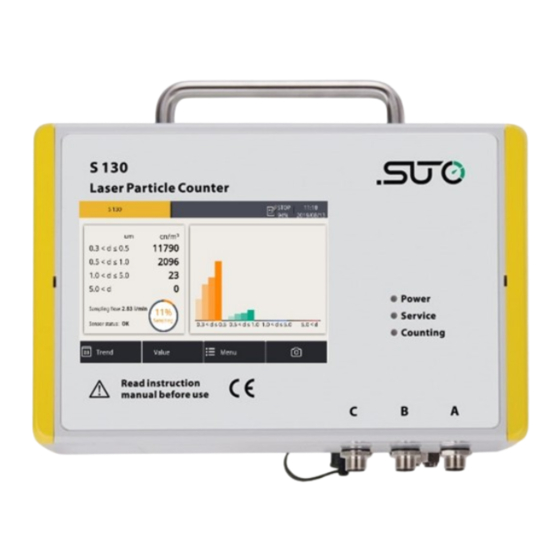
9 Operations using the integrated display 9 Operations using the integrated display If the S130 comes with a display (Item No: S604 1305), you can view the particle counts in real-time and configure the S130 using the display. 9.1 Value view After the S130 is powered on and initialized, the screen displays the value view as shown below. -
Page 19: Icons In The Status Bar
Area Description Shows the progress of the sampling or purging process. The S130 instrument purges sampled data in the first five minutes after powered on. During this period, the progress of “Purging” instead of “Sampling” is displayed. Shows the last four particle counts of each channel in a bar graph. -
Page 20: Trend View
Shows the dynamic graphs of all measurements. To view the trend screen, press Trend in the bottom bar. The trend view is pre-configured in the factory. You can view the S130 measurement graph without configuring anything. To manipulate the graph, follow the instructions indicated in the following figure. -
Page 21: Menu
9 Operations using the integrated display 9.4 Menu Enables you to change the S130 settings. The menu consists of the following function buttons: Sensor settings To change the S130 sensor settings Location settings To customize the sensor name shown on the top... -
Page 22: Sensor Settings
9 Operations using the integrated display 9.5 Sensor settings As stated in Chapter 7, the S130 is delivered with standard ex-factory configuration or with specific customer settings according to the order. Before starting to measure, you can access sensor settings using the Menu >... -
Page 23: Counter Setting
9.5.3 Alarm settings The S130 provides one alarm relay output through the pin 1 and 2 of connector C (NO, 40 VDC / 0.2 A). You can use this output to trigger an external alarm device. -
Page 24: Modbus Settings
To select a channel that is monitored to trigger the alarm output. Threshold To enter the alarm threshold for the monitored channel. 9.5.4 Modbus settings To change the ex-factory Modbus/RTU settings. 9.5.5 Sensor Info To view the sensor information including its type, serial number, and firmware version. S130... -
Page 25: Led Indicators At The Front Panel
The Service LED on indicates that the laser is faulty or the sensor is contaminated. In such cases, make sure that you operate in the specified pressure range and purge the sample air through the device for about ten minutes. If the service indicator is still on, please contact the customer service. S130... -
Page 26: Signal Outputs
11 Signal outputs 11 Signal outputs 11.1 Analog output The S130 provides an analog output range of 4 ... 20 mA. This output is scaled as follows: • 4 mA = 0 • 20 mA = 100000 cn/m 11.2 Modbus Interface... - Page 27 FLOAT 4-Byte Channel 4 cn/m ASCII 8-Byte Unit of counting string** channel Float 4-Byte Analog output scaling, 4mA Float 4-Byte Analog output scaling, 20 mA UNIT16 2-Byte Analog output routing Float 4-Byte Alarm threshold UNIT16 4-Byte Alarm routing S130...
-
Page 28: Alarm Output
The sensor has a relay output with NO, 40 VDC / 0.2 A rating. It is possible to monitor, for example the particle content and give an alarm at a particular value. Alarm relay specifications: Rating: 40 VDC / 0.2 A Power off state: NO (normally open) Default threshold value: 500000 cn/m³ S130... -
Page 29: Optional Accessories
The following diagram shows the connection of the service kit, S130, and the computer. Please ensure that either the S130 or the service kit is connected with the power supply because the USB port cannot supply enough power to both these two devices. -
Page 30: Calibration
It might be necessary to reset the displays storage during calibration and service. 14 Maintenance To clean the device and its accessories, it is recommended to use moist cloth only. ATTENTION! Do not use isopropyl alcohol to clean the display! S130... -
Page 31: Disposal Or Waste
The sensor, the accessories and its packings must be disposed according to your local statutory requirements. The dispose can also be carried by the manufacturer of the product, for this please contact the manufacturer. S130... - Page 32 SUTO iTEC GmbH SUTO iTEC (ASIA) Co., Ltd. Grißheimer Weg 21 Room 10, 6/F, Block B, Cambridge Plaza D-79423 Heitersheim 188 San Wan Road, Sheung Shui, N.T. Germany Hong Kong Tel: +49 (0) 7634 50488 00 Tel: +852 2328 9782 Email: sales@suto-itec.com...
Need help?
Do you have a question about the S130 and is the answer not in the manual?
Questions and answers